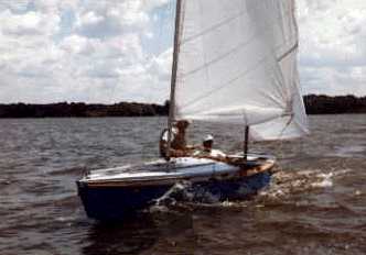
JIM HUXFORD'S BOLGER OTTER
Contents:
Contact info:
Jim Michalak
118 E Randall,
Lebanon, IL 62254Send $1 for info on 20 boats.
Jim Michalak's Boat Designs
118 E Randall, Lebanon, IL 62254
A page of boat designs and essays.
(15Mar99) This is going to be a bit interesting because this issue will be devoted to two subjects I know almost nothing about. First subject will the the prismatic coefficient and the second will be the presentation of a proa design. Next issue, 1Apr99, will show ways to figure the displacement of a design.
NEAT WEB SITE...
Jim Huxford has a great site at www.apci.net/~jhuxford devoted to his heart throb, Sparkman and Stevens boats. Here is how I met Jim. We were both poking around a marina at Carlyle Lake over the Christmas holidays about 10 years ago. Things were frozen hard at the time so it took true boat nuts to be about. He started talking about his Bolger sharpie. I couldn't believe it! Turns out he lives a half mile from here - I still can't believe it! Taught me about computers too. The photo below shows his Otter about 10 years ago at our first Midwest Messabout. It was probably the fastest sailboat we ever had at our messabouts.
TEXAS MESSABOUT...
Tim Webber is once again hosting a messabout in the Houston area on April 16, 17, and 18. For details contact Tim at tbertw@sccsi.com.
|
|
Left:
JIM HUXFORD'S BOLGER OTTER
|
|
|
HISTORY...
Ship design got serious and scientific over 100 years ago when men like Froude started studying the elements of hull resistance through the water. Ships then were strictly "displacement" boats, with no "planing" involved. Resistance was broken into four main catagories. 1) Wave-making. 2) Frictional. 3) Pressure or Form. 4) Air resistance. I'll only discuss 1 and 3 now. Frictional resistance is from the water rubbing past the skin. Air resistance is of the wind against the above water boat.
Waves come mostly from the bow and again from the stern and from any abrupt changes in the hull along its length. All the waves combine in one way or another to make humps and hollows in a resistance curve as the various waves reinforce and cancel each other. Attempts to hang pedictable numbers on the event lead to the "Froude Number". Usually we see the calculation of the Froude Number more in the form of the "speed-length ratio" which is equal to speed (in knots) divided by the square root of the waterline length (in feet). Usually a reasonable maximum speed-length ratio of 1 would be expected from a normal displacement hull although it can be a bit higher. Thus a hull with a 16' waterline length might peak at about 4 knots. A 25' waterline hull would peak at about 5 knots, etc.. The longer the waterline the faster the boat.
It's just a rule of thumb with lots of exceptions. Those of us who row a lot know that there is a lot more involved. For one thing the above rule of thumb makes no allowance for hull shape. For example a fine 16' rowboat will row two or three time faster than a 16' jonboat designed for a gasoline engine.
The Pressure or Form resistance effect is supposed to allow for some of those other factors that separate the faster ones from the slow ones. The form of the hull affects the turbulence and eddying of the hull as the water moves aft.
The wave-making and form resistance elements are often joined together into the "residual resistance".
The idea behind all this was to design a ship, make a small model of the hull and test it in a tank, measuring drag. This to be done at the same speed-length ratio as intended for the full ship, so the model has the same wave pattern as the full sized ship. The frictional drag element of the model can be calculated and subtracted from the whole. Eventually the entire business can be scaled up to the full sized ship and performance or powering requirements determined from the small model tests. That was the whole idea behind the head scratching.
BLOCK COEFFICIENT...
As I said before, some shapes are faster than others. For big ships, where the studies originated, it was found that a rough measure of shape could be the "block coefficient". Figures 1 and 2 show the idea behind the block coefficient.
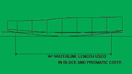
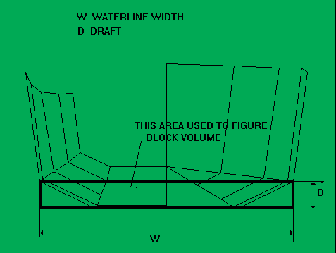
Here is how it's done. Let's say your boat has a waterline length of L, a maximum waterline beam of W and draft of D. Then you might imagine it fitting neatly into a rectangular block with length L, waterline width W and depth D. That block will have a volume of LxWxD. The block coefficient is calculated by dividing the actual volume of your below-the-water hull by the volume of the imaginary rectangular block.
So there are two parts to the puzzle here. The underwater hull volume is determined by the weight of the boat. Once you've defined the underwater hull the L,W, and D, you need to measure the block are easily found.
First you need to know the total weight of your boat and everything in it. Not always an easy number to come by.
The boat's total weight is equal to the amount of water it "displaces" or pushes aside. Fresh water weighs about 62 pounds per cubic foot and salt water at maybe 64 pounds per cubic foot. So if your boat's total weight were 620 pounds it would push aside, "displace", about 10 cubic feet of fresh water.
Next you must push your imaginary design down into the imaginary water until the volume of hull under the waterline equals the volume of water to be displaced at the given weight. This is usually a trial and error calculation that will be explained next issue. Once you find a suitable draft to balance your weight, you measure the waterline length and maximum waterline beam at that draft. Those are the L, W, and D used to size the "block" of the block coefficient. Multiply L times W times D to get the volume of the imaginary "block"
Lastly, you divide the actual displacement by the volume of that imaginary block. That is the Block Coeffiecient.
A hull like a barge which is totally squared off will have a block coefficient of 1, the maximum you could have. If you refined the ends of that square barge and make them pointy and smooth and round you reduce the block coefficient for the design maybe down to .5 and it would go through the water with a lot less waves than the totally rectangular boat, even though it's main cross section is still rectangular.
But let's say you left the ends squared off and got a .5 block coefficient by using a V cross section instead of refined ends?
To avoid that confusion, the concept was refined from the "block" coefficient into the "prismatic" coefficient.
PRISMATIC COEFFICIENT...
This is a refinement of the block coefficient. Imagine you have a V or round sectioned hull, or any section which deviates from a rectangular cross section common on big ships. Then you use the "Prismatic Coefficient". Figure 3 shows how that one is figured.
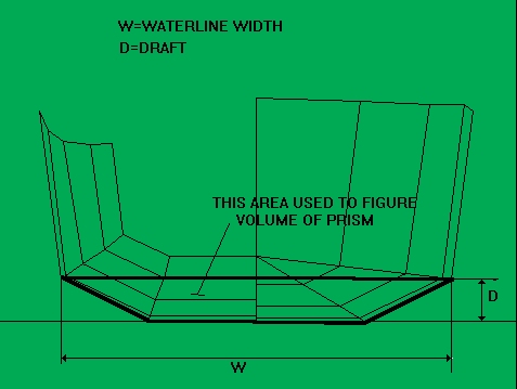
Essentially the prismatic coefficient is figured the same way as the block coefficient except the rectangular block that you figured in the block coefficient is replaced by a similar constant section prism which has the same length as the boat's waterline and a cross section identical to the actual boat cross section.
You can see that the prismatic coefficient sort of takes away the cross sectional element that might confuse the block coefficient calculation. For example you might have two boats with a block coefficient of .5, one with very fine ends and a square cross section, and another with totally square off ends and a V bottom. But if the two were figured using the prismatic coefficient, the first boat would still have a prismatic coefficient of .5 and the second would have a prismatic coefficient of 1!
Anyway, that's all it is.
WHY ALL THE FUSS...
The prismatic coefficient is a rough measure of the fineness of a hull. A square barge will have a prismatic coefficient of 1. If you streamline one end and leave the other end blunt, as with a modern planing powerboat, you might have a prismatic coefficient of .75. If you streamline both ends you might get down to a prismatic coefficient of .5.
But the experimenters tell us the "optimum" prismatic coefficient is about .6. I assume they are talking displacement hulls in fairly smooth water. A check of my old Mechanical Engineer's Handbook shows almost all modern big ships do indeed have a prismatic coefficient of about .6. Some boats like crude oil carriers are closer to .75, apparently the extra volume in the blunter hull being more important than the speed that might be gained from finer ends. The Edmund Fitzgerald came in above .85! (The edition of my book was written before the wreck.)
We see small boat designers pushing the lines of their designs around to get the optimum. Me, I don't think it is anywhere near that simple or worth chasing after for two reasons. First is that our little boats often operate in conditions that are comparativly rougher than those of a large ship. So I'm pretty sure ends finer than the usual optimum might be better for most of us. And the other reason is that if you design almost any normal looking displacement boat, you will almost always end up with a prismatic coefficient between .5 and .6. The .5 value might be for a fine lined rowing boat or sailing boat with nice pointy ends. The .6 is pretty typical of a sailing scow. Yes, the scow with the "ideal" prismatic coefficient should outsail the other boat in smooth water, but the fine ended boat might keep going in rough stuff long after the scow had to go home.
NEXT TIME...
I'll show ways to calculate the displacement of your boat from the lines drawing.
GIZMO
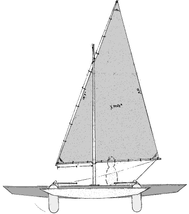
GIZMO, SAILING PROA, 20' X 8', 250 POUNDS EMPTY
I'm finding out folks talk about proas like they talk about sex. Most talk about it a lot more than they do it. The ones who do it a lot don't talk about it.
Gizmo was designed at the urging of Craig O'Donnell who edits the Cheap Pages . In there is section on proas. Like most of you I have never actually seen a real proa but I think it's good practice to do an unusual design once in a while for practice.
Proas don't tack through the wind as would a normal sailboat. Instead they are symmetric about their middle and to reverse direction you reconfigure the rig to sail the other way and take off. What was your stern is now your bow. Is that clear?? If you look at the rig drawing shown above, Gizmo is rigged to sail from right to left. But if the sail were dipped to point the other way, she would sail just the same from left to right. In the case of the lateen sail shown here you might also just let the sail swing around the mast so it points the other way. The balance float which is called an ama is always on the windward side of the main hull. The advantage of the proa is that, under certain conditions, the boat can be very simple and fast. Essentially proas are sailing canoes. The ama provides balance to a rig much larger than can be carried by a normal canoe. With the ama "flying" a bit over the water you have a very slim main hull being pushed by a big rig with a crew sitting in comfort and safety.
But getting this all to work is a challenge. Historical proas were ocean boats in the trade winds and could take their time in tacking, if they ever had to. They steered with a long oar over the current stern and reset the sail with each tack. You can't do that solo or in crowded waters. The rig shown might help having two stout rudders that swing up either way in shallows. The skipper locks one in the straight position and steers with the other and can swap back and forth. I got the idea from Phil Bolger. I don't know if it has ever been tried for real. Phil intended it to steer with the bow end rudder but I think it might steer with either end. The loads on the aft rudder might be quite high so the rudders are "balanced" quite a bit in that the pivot axis is almost on the rudder's centerline and not on its leading edge. These boats are always big experiments and don't expect to get by without a lot of tinkering. I think a proa is a very simple idea that is hard to deliver properly if it must be single handed in crowded waters.
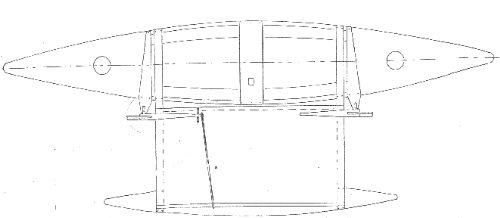
Gizmo is probably sufficient for two adults and no more. Remember it is just a long narrow canoe. I kept the total width at 8' for easy trailering but you could widen it easily. The mast shown is unstayed but is set up so that you can run stays form the masthead to the ama for really hard sailing. The 94 square foot sail looks small for a 20' boat, but big considering the 2' beam of the main hull. Commodore Monroe had something like this in Florida a hundred years ago only 30' long and heavy. It planed although he didn't use that word because it hadn't been invented yet. I'm wondering if it was the first planing boat?
Seven sheets of 1/4" plywood build Gizmo with taped seams. No jigs or lofting. Plans are $20 until one is built and tested.
Prototype News
Some of you may know that in addition to the one buck catalog which now contains 20 "done" boats, I offer another catalog of 20 unbuilt prototypes. The buck catalog has on its last page a list and brief description of the boats currently in the Catalog of Prototypes. That catalog also contains some articles that I wrote for Messing About In Boats and Boatbuilder magazines. The Catalog of Prototypes costs $3. The both together amount to 50 pages for $4, an offer you may have seen in Woodenboat ads. (If you order a catalog from an internet page you might state that in your letter so I can get an idea of how effective this medium is.) Payment must be in US funds. The banks here won't accept anything else. (I've got a little stash of foreign currency that I can admire but not spend.) I'm way too small for credit cards.
Usually when a design from the Catalog of Prototypes starts getting built and is close to launch I pull it from the catalog and replace it with another prototype. So that boat often goes into limbo until the builder finishes and sends a test report and a photo.
Here are the prototypes abuilding that I know of:
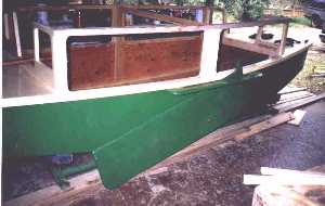
IMB: I heard recently from the Texas IMB builder who said, "I want to let you know that IMB is alive and looking good. She is now right side up and sitting on her cradle. Soon this boat and carrier will be mounted on the small trailer I have ready......" Then I got this photo from Roger Harlow by way of Tim Webber.
Fatcat2: There is an old timer (80 years +) in Minnesota who has completed the hull of a Fatcat2. Fatcat2 is a simple 15' x 6' catboat, gaff rigged and multichined. I think the sail rig will be done this coming winter. Not only has he finished the Fatcat2 hull but he has started a....
Twister. The Twister hull is pretty well cut and fitted, ready to tape. Walt lives north of Green Bay, working in an unheated shed. He tells me there will be no more building until things warm up again next year in late Spring. If you live up there and would like to contact Walt, let me know.
Mixer2: Mixer2 is more or less the original Mixer with a rough water bow like Toto's. 12' x 3'9" and about 90 pounds. Has a sail rig. I got a call from a Colorado builder who wanter to learn to sail and apparently has the boat well along. He also built last year a Smoar which is a 12' version of Roar2 and was very satisfied with it. As I talked with him on the phone I got down on my knees and begged for photos.
Frolic2: I recently heard of two of these going together. One in is Colorado and seems to be on the back burner for now. The other is in Oregon and is on the front burner. He started it in January and is about half done, hoping for an early summer launch.
Herb builds AF3 (archived copy)
Hullforms Download (archived copy)