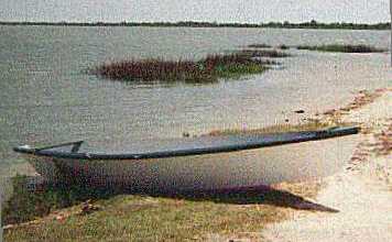
Left:
MARSHALL FOOTE'S SPORTDORY NEAR GALVASTON
Contents:
Contact info:
Jim Michalak
118 E Randall,
Lebanon, IL 62254Send $1 for info on 20 boats.
Jim Michalak's Boat Designs
118 E Randall, Lebanon, IL 62254
A page of boat designs and essays.
(1Jun99) This issue will show how I've been making rudders for my own small boats. Next issue, 15Jun99, will have some thoughts about rigging sharpie sprit sails.
MIDWEST MESSABOUT NOTICE...
The 10th annual Midwest Messabout will take place at the Gun Creek Recreation Area at Rend Lake in Southern Illinois on June 11,12, and 13. The usual routine is that some folks come on Friday and leave early on Sunday. To get to Gun Creek take Interstate 57 to exit 77 West, head towards the golf course on the south side of the road and follow the signs. This is a Corps of Engineers rec area with a $2 launch fee. Camping is 10$ a night and that will cover the launch fee. There is no schedule of events - we just wing it. Email me at michalak@apci.net if you have questions.
|
|
Left: MARSHALL FOOTE'S SPORTDORY NEAR GALVASTON
|
|
|
BACKGROUND...
Here is an article I wrote a while back that appeared in the great paper magazine BOATBUILDER. I've included copies of it in my prototypes catalog since then. The article shows how I've made rudders for my own small boats.
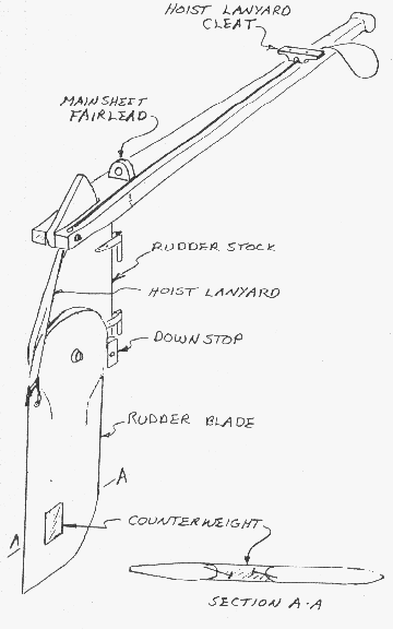
Where I sail only a kick-up rudder works well. It's not because once a year you might strike a ledge and break off a fixed rudder. It's because our waters are generally shallow and a fixed rudder would require endless fussing on every trip. With the weighted kick-up rudder shown here you just blast along without giving the kick-up blade a second thought.
I have also tried kick-up rudders that weren't weighted, but were held down by lanyards. Nearing a shore or shallow I had to play the thing like a puppet and quickly ran out of hands because the tiller, sheet, and board all needed handling at the same time. The weighted rudder blade is much better. In this article I'll show you how I build a kick-up rudder from the ground up from plywood. This sort of rudder can be suitable for boats up to about 22 feet length.
RUDDER BLADE...
The best way to make the blade is to laminate it from thinner plywood. I've seen warped blades made from a single piece of 1/2" plywood, but I've never had a problem with a blade built up from two layers of 1/4" plywood.
Cut out the plywood blanks and butter one up with glue. I prefer plastic resin glue. It comes as a dry powder and is mixed with water to the consistency of regular white wood glue. It's best to spread the glue with a notched trowel like you use to paste down floor tiles. Place the glued-up blanks together on a flat surface protected with plastic or paper, and tap a couple of light nails through them so they can't slide around on each other. Apply clamping pressure with weights like concrete blocks placed atop the blanks. Now stay away until the glue has set good and hard.
Now give the blade a final trimming and streamline the edges where required. (If your rudder, daggerboard, leeboard or centerboard vibrates in use, streamline the edges some more. That almost always cures the ailment.)
SINK WEIGHT...
I called this the "counterweight" in the drawing but "sink weight" is a better term.
The sink weight should be slightly heavier than the buoyancy of the immersed blade. Wood is about half as dense as water, and lead is about 11 times denser than water. It works out that the area of the lead weight should be about 1/16th the area of the immersed blade, or maybe 7 percent of the area to give a slight negative buoyancy. For example, a blade that is 10 inches by 15 inches immersed is 150 square inches. The lead weight could be 150 x .07 = 10.5 square inches, which would be a square 3.24 inches per side. Cut a hole in the blade for the lead to the proper size, preferably toward the tip and toward the trailing edge. Bevel the hole's edges so the lead will lock in place by forming flanges around the blade. Also place some rustproof nails or screws around the interior of the hole to further lock the lead in place. Clamp the blade to a flat metal plate and place it level on the floor.
To figure the weight of the lead required, multiply the area in inches by the thickness in inches and again by .4. In the example, if the example blade is 3/4" thick, the weight of the lead required is 10.5 x .7 x .4 = 3.15 pounds.
To melt the lead, I use a propane camp stove. I place it right next to the job so I woun't have to tote molten lead around the shop. For a crucible I use a coffee can with a 1/2" pour hole drilled about 3" above the bottom of the can, with a long metal handle bolted to the side of the can. The crucible goes on the stove with enough lead wheel weights inside sufficient for the pour.
Begin the pour as soon as the lead is molten. (The steel clamps on the wheel weights will float to the top and not pass through the pour hole.) Take your time and be very careful with the pour, but it must be done all at once. Overfill the hole in the rudder blade somewhat to allow for shrinkage on cooling. Shut off the stove and walk away from the job for a few hours. Lead stays very hot long after it has solidified.
If the weight gets loose in the blade due to shrinkage, you can tighten it by placing the weight over an anvil and hitting the lead with a hammer. That squeezes the center and expands the perimeter.
Now contemplate what it's like to pour a thousand pound keel!

RUDDER STOCK...
Laminate this exactly as you did the rudder blade. You need to add the downstop and it's amazing to me how sturdy this part needs to be. A block of hard rubber or phenolic plastic bolted in place might be best.
TILLER/HOIST LANYARD...
Don't make the tiller too short! Make it too long and shorten it later if needed. The tiller should fold neatly along the back edge of the rudder for storage.
Use light braided line, about 3/16" for the lanyard. Tie it to a small hole in the rudder's trailing edge. The hole needs to be located about where the raised rudder meets the aft end of the tiller. Then pass the lanyard through a hole in the back corner of the tiller, then forward to a small cleat on the top of the tiller. Pass the lanyard through a small hole in the base of the cleat and tie and loop for your fingers. To raise the rudder, yank on the lanyard and belay it around the little cleat. To lower the rudder, uncleat the lanyard and let the blade drop kerplunk against the stop.
SHEET FAIRLEAD...
This works very well on smaller sails that don't require multipart main sheets. Screw a fairlead solidly to the tiller's top face. Place the fairlead right above the rudder hinges so the sheet loads won't affect steering. Run the sail's sheet through the fairlead and forward along the tiller. You can secure the sheet merely by wrapping it a couple of times around the tiller's grip under your steering hand. Then you can steer and hold the sheet with the same hand. To release the sheet in a puff you need only slacken your grip without letting go of the tiller. You can also belay the sheet around the rudder lanyard cleat if you are feeling lucky.
HINGES...
I haven't figured out hinges yet. I think the best ones are welded up from stainless steel, but I'm working towards building boats totally from lumberyard stuff. Stevenson Projects used barrel bolt locks for hinges. Payson used eyebolts and rods. Dick Scobbie used door hinges with big cotter pins for pivots. Seeing those, I tried some door hinges on a dink rudder and was quite satisfied, especially since they came from the scrap bin. Most door hinges won't mount as simply as real boat fittings - check out the angles they swing through and do some head scratching.
One thing I'm sure of: Don't rely on gravity to keep your rudder on your transom. In a knockdown the rudder may unship and leave you with a very wet boat and no rudder. Also, with the sheet fairlead on the tiller as I've shown it, the sheet can produce a large upward force on the assembly in strong winds and lift the whole thing out of conventional fittings. Both of these things have happened to me. Now I secure conventional fittings against knockdowns and sheet loads by drilling as small hole in one pintle below the gudgeon and putting a cotter pin through the hole.
THE CARY HINGE...
I wrote the above a few years ago. But very recently I got letter from Ted Cary in Florida. He has a way of making effective rudder hinges from scrap seatbelts.
Here is his description:
"Thought you might be interested in my solution to the rudder pintle problem. My first experience trying to hit two gudgeons with the pintles in a big chop, while hanging over the transom, disqualified that system for me. I came up with a simple track and slide system, then epoxied up the slide and rudder stock around pieces of connecting webbing strap. The stap flexes when you steer. You can bend a seat belt a lot of times before it breaks, and nylon doesn't corrode in salt water. I found that you must align the strap longitudinally across the direction of the flex, and you must not allow the epoxy to harden on the strap where it has to flex. But the ends of the strap have to be well saturated to hold the slide and the rudderstock halves together. The most successful way I've used to avoid glue where I don't want it is to get the parts all glued up and assembled with clamps, keeping the glue off the flex line as much as possible. Then use a syringe or squirt bottle to saturate the flex line with vinegar, working it through the fibers, before the glue starts to set. The acetic acid neutralizes the amines in the epoxy hardener, so it won't polymerize. The clamped parts won't allow the vinegar to reach the glue on the strapping between them, so it goes off where you want it to."
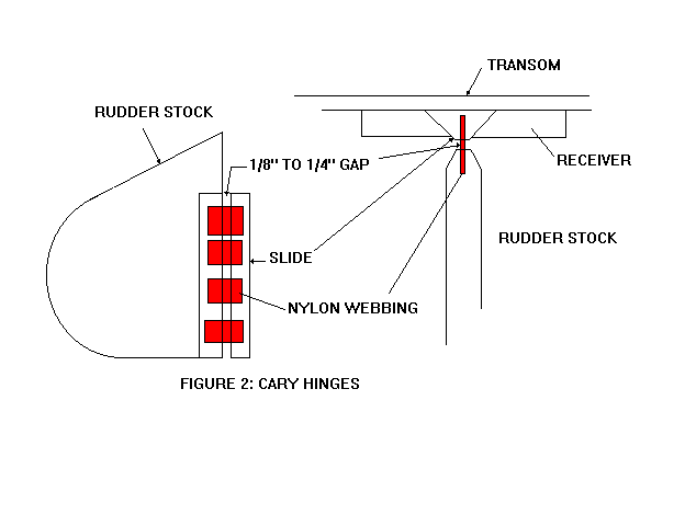
"Dropping the triangular section slide down the transom track installs the rudder in a fraction of a second.This hinge rig has been working great on several dinks for over 4 years now."
Well, I must try Ted's system sometime. I think model airplane guys have been using flexing plastic hinges for a long time. My only comment might be that I would also lock the slide it to prevent it from unshipping in a knockdown.
NEXT TIME...
I'll show how I rig a sharpie sprit sail.
Contents
SCRAM PRAM
SCRAM PRAM, SAILING BEACHBOAT, 16' X 6.5', 500 POUNDS EMPTY
Scram Pram is an interesting boat that I designed for Wil Gordon of Houston a few years ago. He built the prototype shown above, including making that multicolored sail. Wil had owned some production pocket cruisers and had sailed in Karl James' Jewelbox. He wanted a huge rig all in one sail for moving in very light winds. We started the design process by enlarging IMB and it turns out that at least two Scrams have been built while the prototype IMB is still abuilding.
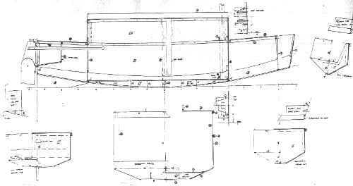
The lines show that Scram has a multichined cross section, like my Piccup Pram, and I've found that makes for a very fast and seaworthy boat. The top is built up like a Birdwatcher. Everyone sits inside, including the skipper. The boat can also be steered by sitting in the open top slot as shown in the photo. The top of the cabin has a slot that runs full length. If you sit to the side you are inside under the deck, but you can stand up in the middle. In bad weather the slot is covered with a snap-on tarp. If you have children this is a good boat type because they will never be on deck. If you use tinted plastic for the windows and a white hull, the boat will be cool in hot weather.
But the main advantage for the Birdwatcher cabin, invented by Phil Bolger, is that the crew sits low and the crew's weight acts as ballast, instead of making a boat top heavy as with a normal cruiser where you sit on a raised deck. Sometimes the effect is so strong that the Birdwatcher boat will be quite self righting with no ballast other than the crew weight. So you can get a nice light simple self righting cruiser. With Scram it didn't quite make it. In tests of the prototype, the boat was just barely self righting with a crew of one against the floor when the boat was rolled over 90 degrees by a rope attached to the masthead. But the design has water ballast tanks on the floor to take 300 pounds of water. With the tanks full the boat is so stable that the test crew had trouble rolling the boat 90 degrees with the mast rope. When released, Scram popped right up. The testing was done by Tim Weber of Houston and was written up in this web site last year. You can access the back issues to review. Tim felt that Scram would be OK with 100 pounds of ballast and that there was little need for more than 200 pounds.
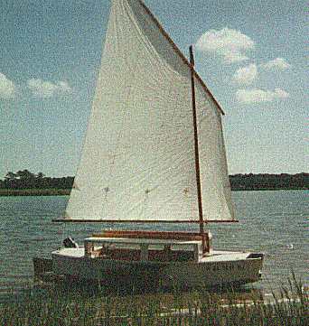
A second Scram was built to prototype plans by UT Roberts of Savannah. His boat is shown above. UT's boat had two significant changes. He reduced sail area to 150 square feet from the original 170+. I made the sail shown in the photo and I feel it is quite enough, especially since the boat has a motor well built in and only 2 or 4 horsepower will push it fine on very light days. Very few people have the patience or time to sail in light flukey winds. Almost any boat this size will end up with a motor which will get used a lot. Then a huge sail rig is not the best thing to have. UT's boat also did not have water ballast. I think he has sand bags lashed below seating benches he has built in, a good option probably if the bags are very low down and very well secured. The idea of bench seating is nice but one must scope out the bench height very carefully to get enough headroom. As is, the water ballast tanks have a foot well. If I were building a Scram, and I would do so if I didn't already have 7 boats in the shed, I would build in the ballast tanks and use the smaller sail.
Scram uses taped seam construction with five sheets of 1/4" plywood, nine sheets of 3/8" plywood, and one sheet of 3/16" dark Plexiglass.
Scram plans are $35.
Contents
Prototype News
Some of you may know that in addition to the one buck catalog which now contains 20 "done" boats, I offer another catalog of 20 unbuilt prototypes. The buck catalog has on its last page a list and brief description of the boats currently in the Catalog of Prototypes. That catalog also contains some articles that I wrote for Messing About In Boats and Boatbuilder magazines. The Catalog of Prototypes costs $3. The both together amount to 50 pages for $4, an offer you may have seen in Woodenboat ads. Payment must be in US funds. The banks here won't accept anything else. (I've got a little stash of foreign currency that I can admire but not spend.) I'm way too small for credit cards.
Usually when a design from the Catalog of Prototypes starts getting built and is close to launch I pull it from the catalog and replace it with another prototype. So that boat often goes into limbo until the builder finishes and sends a test report and a photo.
Here are the prototypes abuilding that I know of:
Fatcat2: There is an old timer (80 years +) in Minnesota who has completed the hull of a Fatcat2. Fatcat2 is a simple 15' x 6' catboat, gaff rigged and multichined. The boat is totally done now, waiting for Green Bay to warm a bit.
Mixer2: Mixer2 is more or less the original Mixer with a rough water bow like Toto's. 12' x 3'9" and about 90 pounds. Has a sail rig. I got a call from a Colorado builder who wanter to learn to sail and apparently has the boat well along. He also built last year a Smoar which is a 12' version of Roar2 and was very satisfied with it. As I talked with him on the phone I got down on my knees and begged for photos.
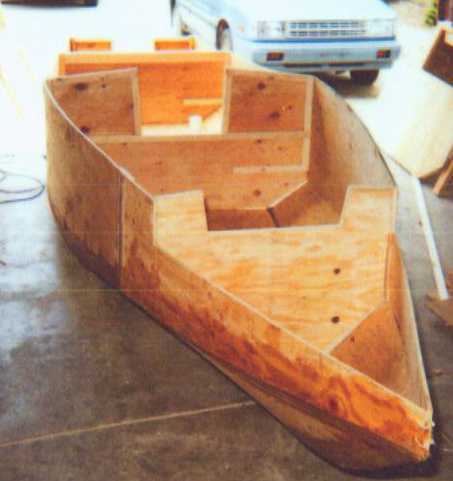
Frolic2: Good news on the Frolic2 front. The first one has been completed and sailed by Larry Martin of Coos Bay, Oregon, ahead of schedule. He reports an excellent first sail on a very rough day. He sailed from the dock downwind in strong winds and whitecaps, down the lake and beating back. (Larry is pretty experienced but I never advise testing of a new boat, especially of an untried design, in rough going.) We should have pictures in a few weeks. The other Frolic2 prototype is in Colorado, hoping for a late summer launch. Here is one of the latest construction photos. The outside seams have been taped.
RB42: This is an 18' rowboat meant for two. It's never been in any of my catalogs but the Canadian builder has it well underway. Imagine the Oracle shown in the 1may99 issue stretched to 18' and you have it.
Mayfly12: A Mayfly12 is going together up in Minnesota. The hull is ready for taping right now.
Contents
SOME LINKS
Herb builds AF3 (archived copy)
Hullforms Download (archived copy)