
A Toto at an Oregon boat show (Terry Lesh's??).
Contents:
Contact info:
Jim Michalak
118 E Randall,
Lebanon, IL 62254Send $1 for info on 20 boats.
Jim Michalak's Boat Designs
118 E Randall, Lebanon, IL 62254
A page of boat designs and essays.
(15jun02) This issue will discuss sail shaping . The 1jul02 issue will continue the topic.
ON LINE CATALOG OF MY PLANS...
... can now be found at Duckworks Magazine. You order with a shopping cart set up and pay with credit cards or by Paypal. Then Duckworks sends me an email about the order and then I send the plans right from me to you. The prices there are $6 more than ordering directly from me by mail in order to pay Duckworks and credit charges. The on line catalog has more plans offered, about 65, than what I can put in my paper catalog and the descriptions can be more complete and can have color photos.

|
Left:
A Toto at an Oregon boat show (Terry Lesh's??).
|
|
|
Sail Shaping
BACKGROUND...I have presented in past issues articles on making sails from common polytarp. Sails made from those articles have worked quite well. In general the sails are made with the one piece tarp which is cut to a predetermined shape, shaped with one or two "darts", which are tapered folds sewn in place, and then rimmed with a sewn in hem with stiffening elements like fiberglass tape and then given sewn in patches in places where the sail will be tied to the spars.
Although the method of making the sail is pretty straight forward, the calculation of the predetermined shape is not. In particular, the size of the shaping darts is critical but not easily calculated. I was hoping to come up with some "rules of thumb" to simplify the process.
WHY SHAPING DARTS....
Sails should be three dimensional surfaces which will get the most out of making the wind pull the boat forward. A good sail will have a surface shape like the wing of an airplane (indeed, some boats have wings for sails) with a "camber", which is a smooth outward curve. Aero scientists have argued for 100 years about the best camber shape - the optimum shape varies with the speed of the wind. I'm not getting into that except to say that Marchaj, the sailor's aero scientist, stated somewhere that the optimum camber for almost all sailing is 10%. So a sail with a width of 10' would curve outward by 1'.
But, you say, many homemade sails are made from flat panels simply cut to shape and hemmed, with no 3D shaping. True. I think the reason they have had some success is that homemade sails are often made from stretchy materials that give and bulge out on the leeward side, making a camber of sorts.
All sails made by sailmakers have this shape sewn right in. Those sails will not lie flat on the floor. This is where most of the witchcraft of sailmaking is applied and sailmakers don't talk much about how it is done. Usually the sails are sewn together from 3' wide cloth. By varying the width of the seams and by cutting and adding seams where needed, they can shape their sails in 3D. If you are interested in real sailmaking, you might try getting info from Sail Rite Kits or the book The Sailmaker's Apprentice.
When I made my first polytarp sail, that is how I did it. I cut the big tarp into 3' wide strips and sewed it all back together like I would a Darcron sail. I worked fine but It was clear that the idea of cutting the thing apart and sewing it back together was not efficient.
My second effort was to use the full sheet of polytarp and slit it where the shaping seams would be and then sew it back together with a gusset over the slit. Then one builder had his wife make a polytarp sail to those instructions but she knew a lot more about sewing than I do. She used regular shaping darts, as are common in tailored clothes, to simulate the varying seams of the sailmaker. I tried it and found it superior!
Eventually I found a way to put all the shaping in one or two darts instead of placing a dart every 3' as the sailmaker does with his material. Four sided sails like the lug and gaff sails I often use need two. Triangular sails need only one! Here is an example, my own Piccup Pram, using a triangular sail:

The Piccup sail went very well. You can barely make out the shaping dart in the photo running from the tack to a dark shaded point in the center of the sail.
The full details of making this Piccup sail in polytarp were presented in the 15jul99 issue of this webpage. You can still look at it by going to the past issues links at the bottom of this page and clicking on "the way back issue archives". That takes you to a large site where the old stuff is stored with an index.
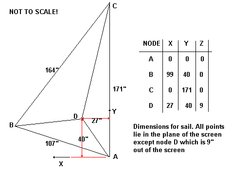
To review, the sail is drawn in "3D", with the perimeter as shown on the boat drawing and with a point in the center of the sail bulging outward. Like this for the sail shown on the Piccup:
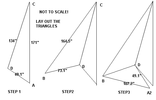
Next the lengths of all the lines shown above are calculated and then the sail is redrawn as a flat pattern with one edge slit like this:
Then this sail flat pattern is drawn out full sized on the polytarp and cut out (with allowances for hems, etc.). When it is sewn up the gap is sewn shut with a "dart" like this:
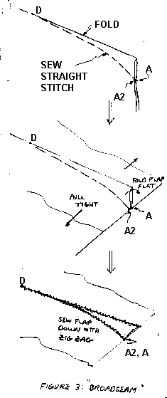
So the final sail is not flat but has a 3D shape to the size and draft specified. It really works!
IF YOU DON'T LIKE DOING MATH...
I thought there might be a way to simplify things a lot by coming up with some rule of thumb for the size of the gap at the tack shown above. When I made the sail shown in the photo I didn't really measure out all the triangular elements. Instead I figured with math that the gap at the tack would be 4.4" and then I drew the pattern of the sail on the tarp with allowance for a 2.2" "dart" at the tack. (A 2.2" dart would remove 4.4" of material from the surface of the tarp which is what is desired.)
But after making a few of these it was clear that the size of the dart is the main thing you needed to know and that the size of that dart was determined, in a triangular sail, mostly by the size of the foot and by the amount of camber. Since I use Marchaj's advice to stick with 10% camber, it all comes down to the length of the foot. Or so I guessed. If true then the instructions for making this sail in polytarp might be simply to "lay it out on the polytarp and sew in a 2" dart at the tack".
I figured a bunch of examples with math to see if my guess was pretty close.
THE FIRST EXAMPLE...
The model I used in the calculations looks like this:
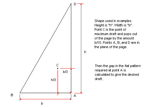
Then I varied the height h and the width b and calculated the flat pattern that would result in the desired sail shape. Then I calculated the the gap at A. Hopefully a pattern would result such that the gap would be more easily calculated.
I ran through several combinations and here is a table of the results:
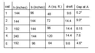
Let's first look at sail 1. It has a luff of 12' and a foot of 8' and a draft of 10% of the foot dimension for 9.6". The flat pattern gap at A needed would be 4.6".
Sail 2 is the same except now it has a foot of 12' instead of 8'. The draft stays at 10% of the foot for 14.4". The gap at A required to build this sail figures to be 9.0". That is an increase of 96% when the foot has been increased by 50%. So it is not in proportion to the foot alone.
Sail 3 is the same as sail 2 except the luff has increased from 12' to 16'. The gap required at A figures to be 8.2", only slightly down from sail2's 9.0".
Sail4 is the same as sail2 except the luff is all the way to 20'. The gap required at A figures to be 7.6". So the length of the luff does not have a huge effect - and increase of 100% in the luff reduces the figured gap from 9" to 7.6", about 15%.
After looking at the effect of the luff dimension on the gap at A, I tried one more in sail5. Sail 5 is the same as sail1 except luff is increased from 12' to 16'. The gap needed at A figures to be 4.1" to give a draft of 10% of the foot, down from 5.2" of sail1.
CONCLUSIONS???
If you were building a normally proportioned sail with an 8' width or foot, I would say the gap at point A would need to be "about 5 inches". A taller sail needs a bit less gap and the lower sail needs a bit more.
If you were building a normally proportioned sail with a 12' width or foot, I would say the gap at A would need to be "about 8 inches". A taller sail needs less and a lower sail needs more.
What if your sail is in between? I cranked through a few more examples to get a feel for it. Sail1 was the basic pattern with a luff of 150% times the foot and a draft of 10% of the foot. Here us what came up:
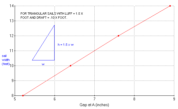
I would use this chart for triangular sails of normal proportions. It starts with a 48 sq foot sail which is about the smallest sail useful. And progresses to a 147 square foot sail, which is about the largest sail I would try with normal polytarp technology. Somewhere in between should be the A gap you are looking for.
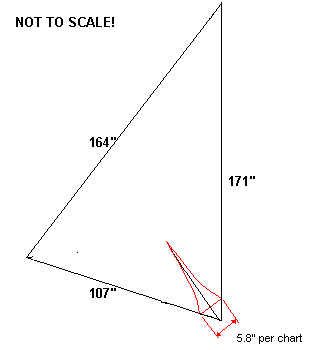
I guess the way I would use make a sail this way would be to lay out the sail according to the basic dimensions shown in the plans, and then draw a line from the tack upward where I want the dart to run, about 1/3 to the top of the sail and 1/3 back from luff. Then at the tack I would draw the "gap" that is predicted by the chart and sew in a dart that would remove that amount of material. The resulting sail will be a few inches smaller than the blueprint sail but that should be of no consequence.
Here is how it might look for the sail I used on the Piccup Pram. The width of the sail is almost 9' and the chart predicts a gap at A of 5.8". I would draw it out like this, fold it on the black line going from the tack to the center of the sail, and then sew in a dart more or less on the red lines shown.
NEXT TIME...
I'm going to try to carry this discussion to four sided sails.
Contents
JONSBOAT
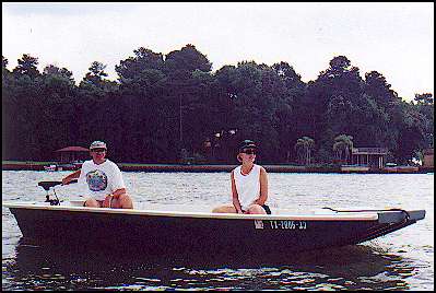
JONSBOAT, POWER SKIFF, 16' X 5', 200 POUNDS EMPTY
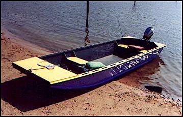
Jonsboat is just a jonboat. But where I live that says a lot because most of the boats around here are jonboats and for a good reason. These things will float on dew if the motor is up. This one shows 640 pounds displacement with only 3" of draft. That should float the hull and a small motor and two men. The shape of the hull encourages fast speeds in smooth water and I'd say this one will plane with 10 hp at that weight, although "planing" is often in the eye of the beholder. I'd use a 9.9 hp motor on one of these myself to allow use on the many beautiful small lakes we have here that are wisely limited to 10 hp. The prototype was built by Greg Rinaca of Coldspring, Texas and his boat is shown above when first launched with a trolling motor. But here is another one finished about the same time by Chuck Leinweber of Harper, Texas:
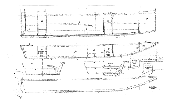
In the photo of Chuck's boat you can see the wide open center that I prefer in my own personal boats. To keep the wide open boat structurally stiff I boxed in the bow, used a wide wale, and braced the aft corners.
I usually study the shapes of commercial welded aluminum jonboats. It's surprising to see the little touches the builders have worked into such a simple idea. I guess they make these things by the thousands and it is worth while to study the details. Anyway, Jonsboat is a plywood copy of a livery boat I saw turned upside down for the winter. What struck me about that hull was that its bottom was constant width from stem to stern even though the sides had flare and curvature. When I got home I figured out they did it and copied it. I don't know if it gives a superior shape in any way but the bottom of this boat is planked with two constant width sheets of plywood.
Greg Rinaca put a new 18 hp Nissan two cycle engine on his boat, Here is a photo of it:
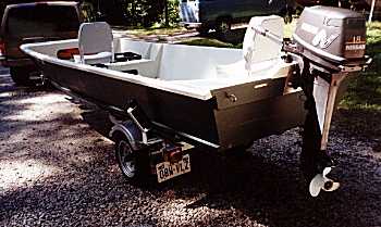
The installation presented a few interesting thoughts. First I've been telling everyone to stick with 10 hp although it's well known that I'm a big chicken about these things. Greg reported no problems and a top speed of 26 mph. I think the Coast Guard would limit a hull like this to about 25 hp, the main factors being the length, width, flat bottom, and steering location. Second, if you look closely at the transom of Greg's boat you will see that he has built up the transom in the motor mount area about 2". When I designed Jonsboat I really didn't know much about motors except that there were short and long shaft motors. I thought the short ones needed 15" of transom depth and didn't really know about the long shafts. Jonsboat has a natural depth of about 17" so I left the transom on the drawing at 17" and did some hand waving in the drawing notes about scooping out or building up the transom to match the requirements of your motor.
I think the upshot of it all is that short shaft motors need 15" from the top of the mount to the bottom of the hull and long shaft motors need 20". There was a lot of discussion about where the "cavitation" plate, which is the small flat plate right above the propellor, should fall with respect to the hull. I asked some expert mechanics at a local boat dealer and they all swore on a stack of tech manuals that a high powered boat will not steer safely if the cavitation plate is below the bottom of the hull, the correct location being about 1/2" to 1" above the bottom. But Greg had the Nissan manual and it said the correct position is about 1" BELOW the bottom. Kilburn Adams has a new Yamaha and its manual says the same thing. So I guess small motors are different from big ones in that respect.
But it seems to be not all that critical, at least for the small motors. Greg ran his Jonsboat with the 18 hp Nissan with the original 17" transom for a while and measured the top speed as 26 mph. Then he raised the transom over 2" and got the same top speed!
There is nothing to building Jonsboat. There five sheets of plywood and I'm suggesting 1/2" for the bottom and 1/4" for everything else. It's all stuck together with glue and nails using no lofting or jigs. I always suggest glassing the chines for abrasion resistance but I've never glassed more than that on my own boats and haven't regretted it. The cost, mess, and added labor of glassing the hull that is out of the water is enormous. My pocketbook and patience won't stand it. Glassing the chines and bottom is a bit different because it won't show and fussy finishing is not required.
Plans for Jonsboat are $25.
Prototype News
Some of you may know that in addition to the one buck catalog which now contains 20 "done" boats, I offer another catalog of 20 unbuilt prototypes. The buck catalog has on its last page a list and brief description of the boats currently in the Catalog of Prototypes. That catalog also contains some articles that I wrote for Messing About In Boats and Boatbuilder magazines. The Catalog of Prototypes costs $3. The both together amount to 50 pages for $4, an offer you may have seen in Woodenboat ads. Payment must be in US funds. The banks here won't accept anything else. (I've got a little stash of foreign currency that I can admire but not spend.) I'm way too small for credit cards.
Here are the prototypes abuilding that I know of:
Electron: The California Electron is coming along. Right now a four cycle 2 hp outboard has been purchased so the original electric idea may wait a while.
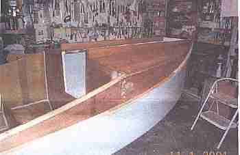
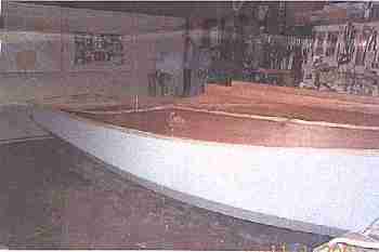
Shanteuse: The stretched (16' to 24') Shanteuse is about done.

Sowsear: Just heard of a prototype Sowsear going together very quickly in Pennsylvania.
AN INDEX OF PAST ISSUES
Hullforms Download (archived copy)
Plyboats Demo Download (archived copy)
Brokeboats (archived copy)
Brian builds Roar2 (archived copy)
Herb builds RB42 (archived copy)