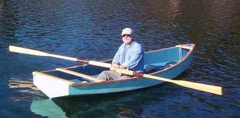
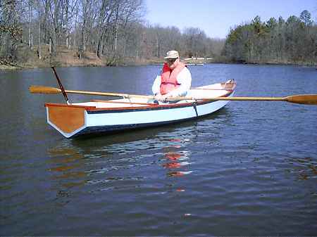
Don Rodgers' Vamp out in California. And he made those beautiful oars too!
Contents:
Contact info:
Jim Michalak
118 E Randall,
Lebanon, IL 62254Send $1 for info on 20 boats.
Jim Michalak's Boat Designs
118 E Randall, Lebanon, IL 62254
A page of boat designs and essays.
(15mar03) In this issue we'll present a homemade gadget to measure propellor pitch. Next issue will rerun the bevels essay and present All The World's Totos.
THE BOOK IS OUT!
BOATBUILDING FOR BEGINNERS (AND BEYOND)
is out now, written by me and edited by Garth Battista of Breakaway Books. You might find it at your bookstore. If not check it out at the....ON LINE CATALOG OF MY PLANS...
... can now be found at Duckworks Magazine. You order with a shopping cart set up and pay with credit cards or by Paypal. Then Duckworks sends me an email about the order and then I send the plans right from me to you.

|
Left:
Don Rodgers' Vamp out in California. And he made those beautiful oars too!
|
|
|
Propellor Pitch
THE VERY BASICS...Boat propellors are sometimes called "screws" because they basically work the same way as a screw. Screw propellors replaced paddle wheels pretty quickly in the early steamship days.
I suspect the first ones may have had blades that were continuous over a few revolutions, more like an auger. The motor guru added: "Francis Petit-Smith apparently conceived of the use of Archemedes water-lifting screw as a propulsion device. He built a full-size prototype, powered with a "screw" shaped much like a screw. While testing, an object in the water was struck, causing the a good prortion of the long "screw" to break off, and the resulting short section continued to push the boat, but at greater speed. John Erickson, designer of the Union ironclad Monitor, was also involved in these trials, and received much credit for the ultimate design of the propeller."
The English also led the way. They proved the point in the early 1800's by making two steamships identical except one had paddlewheels and the other screws. They tied them together for a tug of war and the screw boat easily out tugged the paddlewheeler. The motor guru adds: "The paddle-wheel powered HMS Electo and the propeller-driven HMS Rattler were the two ships in the Tug-of-war."
Anyway, if you take a screw with say 16 threads to the inch and run it into a board, it should take 16 turns to move it forward and inch because that is the pitch designed into it. Boat propellors work the same way, with a designed pitch. They proceed forward a certain amount with each turn.
Here is a picture of a prop:
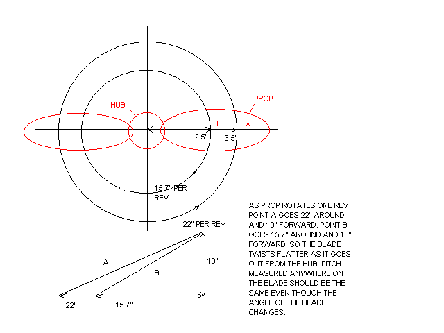
Let's say this one has a 10" diameter and a 10" pitch (actually a common size for a 20hp or so outboard). Look at point A which is 3.5" from the center. As the prop turns a revolution that point will travel pi times 3.5 times 2 = 22". That point will also travel forward 10" (by definition as a 10" pitch) with that revolution assuming no slip so the angle the props face moves through is 10 to 22 which is 24 degrees. Now look at point B which is 2.5" out from the center. That point will turn 15.7" with each rev (pi x 2 x 4.5 =15.7) but travels forward the same 10" as point A. So the prop face there moves through an angle of 10 to 15.7 which is 32 degrees. And so forth along the entire face so that you see as you move from the hub to the tip the blade twists to have a flatter angle. I would think that any effort to "repitch" a proper propellor would be a compromise because you won't be twisting the area near the hub as much as that near the tip.
"But," you say "I can tie my boat to the dock and run it full throttle and it won't move." True, boat propellors do "slip" (aircraft propellors too). I used to think of it like a car's wheels spinning on ice. That isn't the case with a prop in the water. The wide open motor tied to the dock is still putting out its full power but now the power is moving water instead of moving the boat. When I drive over a Mississippi River bridge I'll see huge towboats pushing a dozen big barges (they say over three dozen big barges below Cairo, the largest moving acreage on earth). Thousands of horsepower but no more speed than a jonboat with 10hp. Their wake is not that big but you don't want to boat behind one (or in front of one for that matter) because that big power produces a huge rolling "race". As they push forward a huge amount of water is being force backward and you can see it. With a light boat going full speed the situation changes to where the power goes almost all towards pushing the boat forward.
This year I hope to scope out the slip situation first hand. If you know the rpm of the propellor and its pitch you can figure out how fast it would be going with no slip. Then on the real boat you can measure the speed with a gps and the difference would be the slip. Max says he has a tach, I have a gps, we need to know the prop pitch and the gear ratio of the lower unit. Then for the ice to melt and boat testing.
That would satisfy curiosity for those of us who are easily entertained. But a more serious reason to measure pitch would be to match the prop to the boat. Let's say you have a 10hp motor that pushes a light jonboat 20mph and all is well because the boat's top speed and the engine's redline happen at the same time because the prop is correct. You put the same engine on a heavy shantyboat and now full throttle gives maybe 8mph. Sort of like taking the engine/transmission out of your Ferrari and putting it in your dump truck who's engine had the same horsepower. The power may be the same but your truck won't go 200 mph like the Ferrari did. In fact if the engine can't rev up to its power band it won't go as fast as the old truck engine/transmission did. (People who do a lot of biking with multispeed bikes know first hand of all the situations where you need to shift down to go faster.) So you would think the shantyboat installation would prefer a flatter pitch prop that will allow the motor to deliver its horsepower revs at a lower forward speed than the jonboat propellor.
MEASURING PROPELLOR PITCH...
Looking back to the picture of the ideal prop you see you can measure the pitch anywhere on the blade and should always get the same answer because if properly designed all sections of the prop have the same pitch. All you have to know is the angle of the face and the distance from where the angle measurement was taken to the prop's center.
Here is the simple gadget I made to do that.
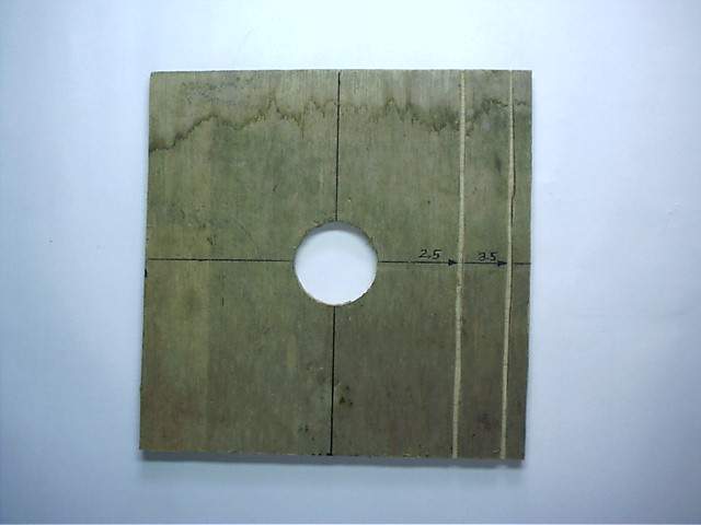
Start with a 10" square of plywood. Draw crosshairs on it. In this case I cut a 1.5" diameter hole in the center to allow it to be used with props already mounted on the motors but the hole is better omitted otherwise. Then I cut narrow grooves out 2.5" and 3.5" from the center.
I cut out a bunch of angle templates from index card stock and labeled them for angle and pitch. They look like this:
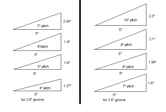
So to measure the pitch of a prop you first place it centered on the plywood with its aft face against the wood because it is the angle of the aft face that is easiest to measure (because the aft face is usually flat). The center of the blade to be measured should be centered over the crosshair that passes over the grooves. Not always easy to do that as you see here with a "semiweedless" curved blade from an old OMC.

Next we slip the angle templates into the most appropriate groove until we have a match, like this:
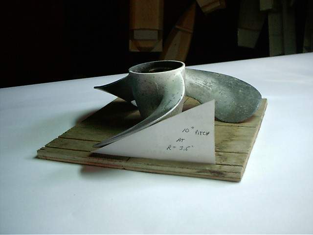
I used the 3.5" groove here but with a smaller prop I would use the 2.5" groove. But remember that you need a different set of angle templates for each groove. Here is another view:
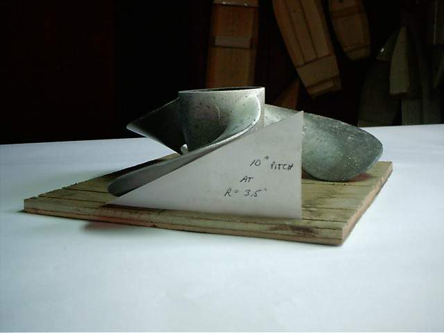
It isn't totally exact because the face of the prop often isn't exactly flat. (I think the "perfect" way to measure the pitch would be to get the angle that goes through the the tip of the leading edge and the tip of the trailing edge. )
There you have it. This old OMC prop measured out at 10 inches of pitch.
NEXT TIME: We review ways of cutting bevels on bulkheads, etc.
Veep14
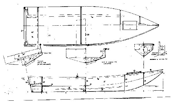
VEEP14, POWER SKIFF, 14' X 4', 160 POUNDS EMPTY
I've tried several different ways to shape a hull to handle rough water. Rough water is a problem around here where the manmade lakes are flat and wide and shallow. We get whitecaps when the wind blows about 12 mph. I think the situation is about the same in a lot of places, like the Gulf Coast and the Chesapeake. When you do a power boat that is supposed to plane the situation becomes critical from the standpoint of control and of pounding to destruction of the hull or of the skipper. In boats like Brucesboat and Dorado I tried it with multichines to give a bit of a flat bottom. That makes the boat easier to use, I think, because it will beach sitting straight up and you will have a bit of a flat to walk on. I've also shaped the bow as in Twang to make the boat meet a wave a little bit at a time instead of with a sudden bang as with a flat bow. But the problem with a planing boat is that at speed it won't meet the water with its bow. Instead it will rise out of the water to meet it with its mid bottom. So with Veep14 I tried a V bottomed skiff.
Veep14 might be a handy all around small skiff which I would hope would take some rough water. (I see a bit of falseness in the idea that it would be "safer" than a flattie because the skipper might be tempted to venture forth in worse and worse weather while the flattie skipper will clearly chicken out and stay in protected areas. So when the V bottomed skipper finally gets in over his head it might be during weather in which no one will attempt rescue.) Veep14 has a constant V all the way along the bottom twisting to a high deep V bow in the forward third. The V reduces the capacity of the boat compared to a flat bottomed job. In this case it would be about 600 pounds maximum which would include the weight of the hull, motor, and gear. That might amount to 300 pounds so you see it is a two man boat at the most.
I've been warned that a V boat like this will need significantly more power than a similar flattie. By the size and shape and layout of Veep14 the usual Coast Guard advice would be for 15hp maximum. I would expect it to need that much to plane at max weight.
My original hope was to make this boat 12' long and light enough to cartop. But I convinced myself that it would be a one person boat if that short and that would be a mistake. And if it were light enough to cartop it might also be too flimsy to take the rough water it was intended to face. So I made it longer and used 3/8" plywood instead of the 1/4" I would use for a cartopper. The weight went up to the point where it will need a trailer but then again a 15hp motor is going to weigh close to 100 pounds and no one will carry around something like that more than once if he can avoid it.
Construction is taped seam needing four sheets of 3/8" plywood for the basic hull and one sheet of 1/4" plywood for the bulkheads and decks.
Plans for Veep14 are $20 until one is built and tested.
Prototype News
Some of you may know that in addition to the one buck catalog which now contains 20 "done" boats, I offer another catalog of 20 unbuilt prototypes. The buck catalog has on its last page a list and brief description of the boats currently in the Catalog of Prototypes. That catalog also contains some articles that I wrote for Messing About In Boats and Boatbuilder magazines. The Catalog of Prototypes costs $3. The both together amount to 50 pages for $4, an offer you may have seen in Woodenboat ads. Payment must be in US funds. The banks here won't accept anything else. (I've got a little stash of foreign currency that I can admire but not spend.) I'm way too small for credit cards.
Here are the prototypes abuilding that I know of:
The Australian Twang builder is done and is testing, searching for the ideal seating position.
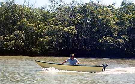
The Oracle builder in St. Louis is done and afloat right side up. Writeup soon.
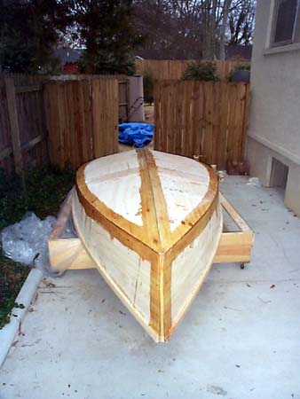
The Alabama Skat is getting its seams taped.
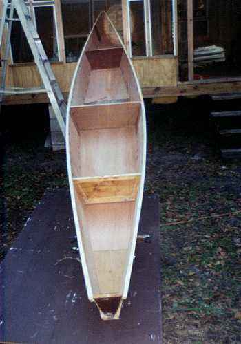
A Piragua18 is being completed in Georgia:
AN INDEX OF PAST ISSUES
Hullforms Download (archived copy)
Plyboats Demo Download (archived copy)
Brokeboats (archived copy)
Brian builds Roar2 (archived copy)
Herb builds AF3 (archived copy)
Herb builds RB42 (archived copy)