
Steve Bird has a rare Mixer2.
Contents:
Contact info:
Jim Michalak
118 E Randall,
Lebanon, IL 62254Send $1 for info on 20 boats.
Jim Michalak's Boat Designs
118 E Randall, Lebanon, IL 62254
A page of boat designs and essays.
(15Jun04) This issue repeats the all important sail area math essay. The 1July issue will present the 15th Midwest Messabout if I can round up photos by then. Otherwise ????
THE BOOK IS OUT!
BOATBUILDING FOR BEGINNERS (AND BEYOND)
is out now, written by me and edited by Garth Battista of Breakaway Books. You might find it at your bookstore. If not check it out at the....ON LINE CATALOG OF MY PLANS...
...which can now be found at Duckworks Magazine. You order with a shopping cart set up and pay with credit cards or by Paypal. Then Duckworks sends me an email about the order and then I send the plans right from me to you.

|
Left:
Steve Bird has a rare Mixer2.
|
|
|
Sail Area Math
BACKGROUND...I have to rerun this essay every year. This subject is the most common area where tinkerers of designs get in trouble. It always has been and always will be. Anytime you modify the sail rig you need to keep this math in mind.
If you look at the picture below of the sail rig of Mayfly12 you will see on the sail some (fuzzy) writing (that didn't scan well) that says "55 square feet" to the left of a small circle that represents the center of that area (honest).
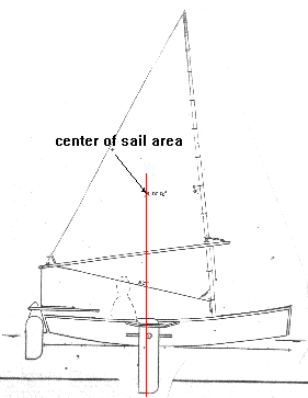
The center of that area is often called a "centroid" and you will see it is placed more or less directly above the center of the leeboard's area. That is very important.
As you might imagine a shallow flat hull like this with a deep narrow leeboard wants to pivot around that leeboard. If the forces of the sail, which in a very general way can be centered at the sail's centroid, push sideways forward of the leeboard, the boat will tend to fall off away from the wind. You should be able to hold the boat on course with the rudder but in that case the rudder will have "lee helm" where you have to use the rudder to push the stern of the boat downwind. The load on the rudder will add to the load of the leeboard. Sort of a "two wrongs make a right" situation and generally very bad for performance and safety in that if you release the tiller as you fall overboard the boat will bear off down wind without you.
If the centroid is aft of the leeboard you will have "weather helm", a much better situation. The rudder must be deflected to push the stern towards the wind and the force on it is subtracted from the load on the leeboard. Not only that, but when you release the tiller as you fall overboard the boat should head up into the wind and stall and wait for you if you are lucky. It's a good deal but if you overdo it you can end up with too much load on the rudder.
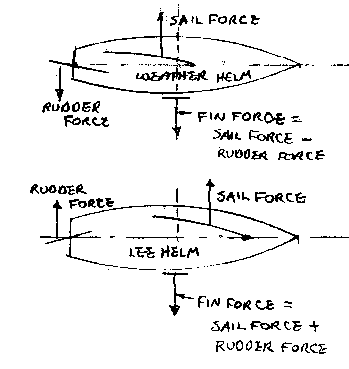
This balance problem is actually one of the few things about sail rigs that is not arbitrary. The type of rig and its area are pretty arbitrary depending on how fast you want to go, how much you weigh, etc. But balance is quite important and is one of the areas where backyard boaters get into trouble, sometimes changing the boat or rig with no thought of balance. So before you go doing that you should do a little homework. This essay will tell you how to figure sail area and find the centroid.
One last item: the balance situation shown for Mayfly12 is what I have found to be best for this type of boats. Boats with large fin keels don't balance that way - usually the sail centroid is well forward of the keel centroid. That distance is called the "lead". That type of boat is not within my personal experience and I'm not going to get into that. But you still would have to figure the area and centroid.
THREE SIDED SAILS...
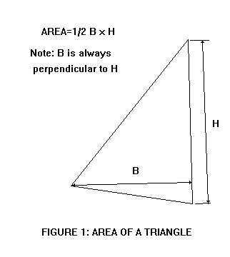
This one is really easy. The area is just the base time the height divided by 2. Any side can be the base and the height is aways at a right angle to the base.
So when you lay out the sail you draw it up on thin paper to the same scale as your hull drawing with the leeboard (or daggerboard or centerboard) lowered. Draw a line through the center of the board straight up. Now we're going to locate the scale sail on the boat such that it's centroid falls very close to that line.
Here's how you find the centroid of a triangular sail.
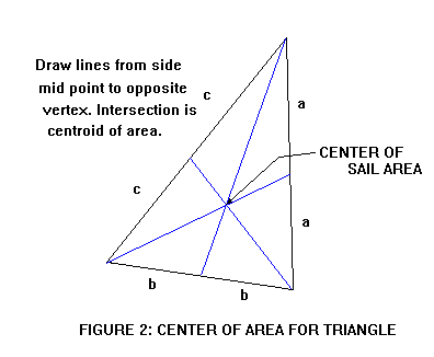
Find the midpoint of each side and and draw a line from that midpoint to the vertex opposite it. The three lines will intersect at the centroid. Actually you only need to find the intersection of two lines but the third line is a good check.
That's it! Now you can take you scale sail drawing and slide it around your hull drawing until the centroid is on that line drawn up from the hull's board. Move it up and down and tilt it until you like the way it looks. But don't cheat much forward or aft of that line.
FOUR SIDED SAILS...
To find the area of a four sided sail you just divide it into two triangles, find the area of each triangle as above, and add the two together.
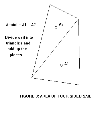
Now to find the centroid of the four sider. Start by finding the centroids of the two triangles that make up the four sided sail as shown above. Now draw a line from one triangle centroid to the other. The centroid of the four sider is on that line somewhere.
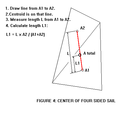
To find exactly where the centroid is on that line, measure the length of that connecting line. You need not use the same scale as is used on the drawing. I prefer to use a millimeter scale for this measurement. Then get out the calculator and work the formula shown in the Figure 4. Let's say for example the length of the connecting line on the scale drawing measures 120 mm (that is measurement L). Let's say the example sail has a lower triangle area of 50 square feet (that is A1). The upper triangle is 35 square feet (that is A2). So the total sail area is 50 + 35 = 85 square feet. The length L1, which will exactly locate the sail's total centroid, is L1 = 120 x 35/85 = 49.4 mm. So you take that millimeter scale and measure up from A1 centroid on the connecting line 49.4 mm and make a tick mark on the connecting line. That is the centroid of the total sail.
Another way to find the centroid, especially of a really odd shaped sail, is to take the scale drawing of the sail and cut it out. Then balance the cutout on a knife edge and mark the balance line, rotate the cutout on the knife edge about 90 degrees and rebalance and mark the new balance line. The centroid lies at the intersection of the two line.
Another way is to dangle the cutout on a pin stuck through a corner and into a wall marked with a vertical line that passes through the pin point. Mark the line that passes through that pivot corner and a vertical. Then rotate the cutout to hang it from another corner, and mark a second line through the second pivot corner and a vertical. The centroid lies at the intersection of those two lines. Back at the missle factory the designers had a favorite place, complete with pivot pin socket hole and vertical line, to hang these cutouts and that place was known as the "weighing wall". Meanwhile the super computer cranked away next door but its answers weren't to be trusted unless they agreed with the cutout hanging at the weighing wall.
RIGS WITH MANY SAILS...
Figure 5 shows the rig for Viola22. It has a main gaff sail of 177 square feet, and a mizzen sail of 45square feet. Where is the centroid of the assembly?
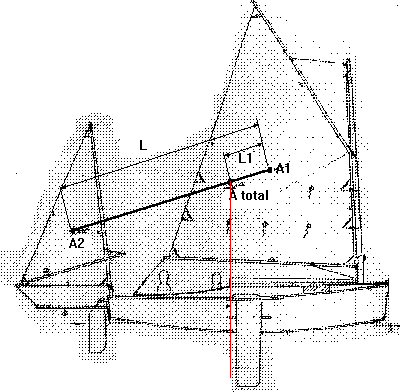
It's done exactly as with Figure 4. Draw a line connecting the areas of the two sails. Measure the length of the connecting line. Then run through the same equation as in Figure 4. Nothing to it.
One thing I might point out about the Viola22 rig is that the total centroid falls near the aft edge of the leeboard. By my experience the mizzen is not as efficient as its area suggests so it needs to be a bit oversized by normal rules, fudging the total centroid aft. I think in general the aft sails operate in the scrambled flow of the forward sail, causing loss of force back there.
NEXT TIME...
...We'll look at the last Midwest Messabout at Rend Lake.
Cormorant
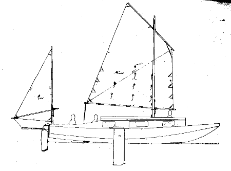
CORMORANT, CABIN SAILBOAT, 32' X 8', 2000 POUNDS EMPTY
Cormorant is the largest boat I've ever designed. I always warn folks to think twice and three times before building a big boat because you can buy a good used glass boat for less, maybe a lot less. But a homebuilt boat can have features that aren't available in a production boat and so it is with Cormorant. This one is really a 20% enlargement of Caprice, Chuck Leinweber's prototype shown here:
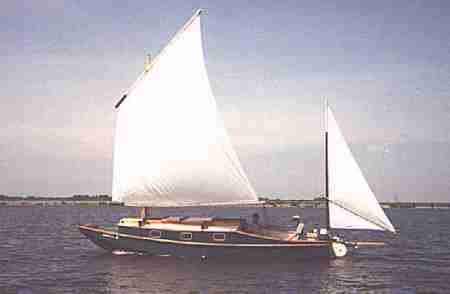
Straight enlargements rarely work perfectly and so it was with Cormarant from Caprice. (Don't forget that Caprice was an enlargement of Frolic2, etc., etc., right on down to my Toto canoe.) In this case I narrowed it from a straight enlargement to keep the width within simple towing limits since this large boat is supposed to live on its trailer most of the time. The layout is quite similar. The idea is that the adults sleep in the center cabin and the kids sleep in the forward room.
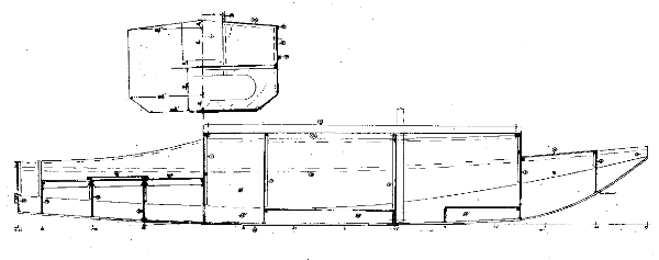
Like Caprice, Cormorant has water ballast, over 1000 pounds of it. Total floating weight with family is going to be up to 4000 pounds. You don't tow a boat this large behind a compact car but I think towing this sort of weight is common today, all done with expensive large trucks I'm afraid.
The sail rig looks pretty modest with a 207 sq foot main. I'll bet it is enought since this shape is easily driven. I don't think you can go any larger and still hope to handle it without extra crew and gear.Tthe lug sail shown is similar in size to Bolger sharpies and they seem to get by OK. Experience will show if it is too big/too little.
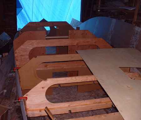
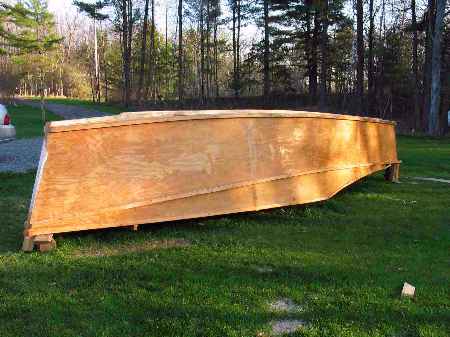
The man who ordered the design has been working on it through the New York winter and has it 3D recently but still upside down. Hard to step back and admire your work on a project this large. He has lots of small boat experience and is doing a great job.
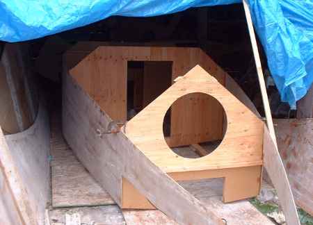
Constuction is taped seam, with no jigs or lofting. Unlike smaller designs this one does not come with a plywood panel layout drawing. Over the years I've learned two things about the ply layout page. First is that almost no one uses it. Second is that with a larger boat the work of finding and drawing and fitting all the pieces to the boat on scale plywood sheets overwhelms all the other work. So part of the deal with doing the design was that there would be no plywood layout drawing. However this is still a true "instant boat" in that all of the parts that define the boat are drawn in detail and you can scale them up on plywood, cut it out and fasten together with no need for lofting or a building form.
Prototype plans for Cormorant are $50 until a prototype is built and tested.
Prototype News
Some of you may know that in addition to the one buck catalog which now contains 20 "done" boats, I offer another catalog of 20 unbuilt prototypes. The buck catalog has on its last page a list and brief description of the boats currently in the Catalog of Prototypes. That catalog also contains some articles that I wrote for Messing About In Boats and Boatbuilder magazines. The Catalog of Prototypes costs $3. The both together amount to 50 pages for $4, an offer you may have seen in Woodenboat ads. Payment must be in US funds. The banks here won't accept anything else. (I've got a little stash of foreign currency that I can admire but not spend.) I'm way too small for credit cards.
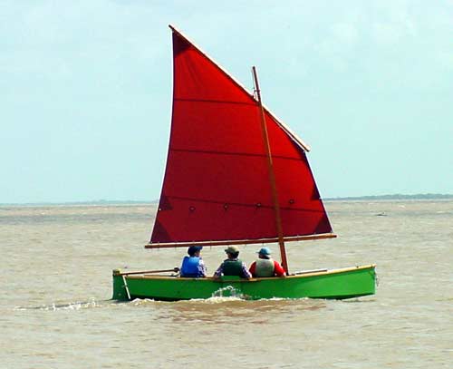
The Texas Ladybug is done! Complete story in a few weeks:
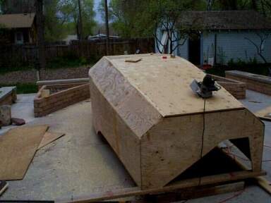
Out West the Picara picks up where it left off before the winter:
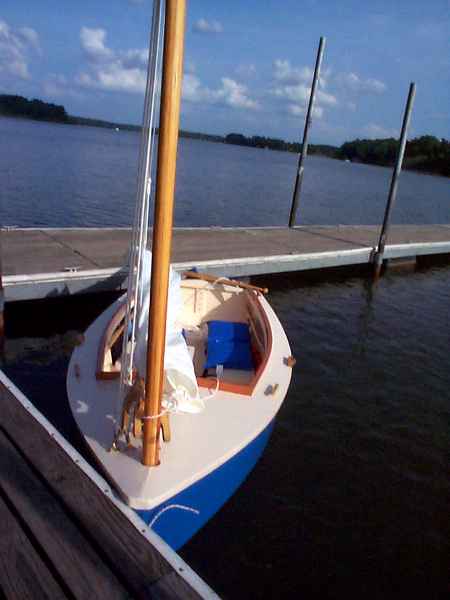
The Deep South Skat is done! Hopefully a full story in a few weeks:
Another Picara, this one with a 1' stretch in the middle, going together in Arkansas. Sailmaking done and its on to glassing the hull.
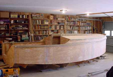
This is an AF4Grande (upside down):
AN INDEX OF PAST ISSUES
Hullforms Download (archived copy)
Plyboats Demo Download (archived copy)
Brokeboats (archived copy)
Brian builds Roar2 (archived copy)
Herb builds AF3 (archived copy)
Herb builds RB42 (archived copy)