
Jim Hauer & co. try out the new River Runner in Green Bay.
Contents:
Contact info:
Jim Michalak
118 E Randall,
Lebanon, IL 62254Send $1 for info on 20 boats.
Jim Michalak's Boat Designs
118 E Randall, Lebanon, IL 62254
A page of boat designs and essays.
(15Apr05) This issue will start the panel expansions on Bobsboat. The 1May issue will rerun the bulkhead bevel essay.
THE BOOK IS OUT!
BOATBUILDING FOR BEGINNERS (AND BEYOND)
is out now, written by me and edited by Garth Battista of Breakaway Books. You might find it at your bookstore. If not check it out at the....ON LINE CATALOG OF MY PLANS...
...which can now be found at Duckworks Magazine. You order with a shopping cart set up and pay with credit cards or by Paypal. Then Duckworks sends me an email about the order and then I send the plans right from me to you.
THE 16TH MIDWEST HOMEBUILT BOAT MESSABOUT will take place at Rend Lake in Southern Illinois on the weekend of June 11 and 12. Remember that lots of folks come on Friday and leave early Sunday. Take I-57 to exit 77W and then follow the signs to the Gun Creek Recreation Area. Camping at this Corps of Engineers facility is $10/night and that includes the ramp fee. There is no schedule of events except a pot luck dinner in the campground on Saturday evening - we wing it. This year some of us have reserved the campsites on the water of the two middle camping loops so look for us there if we aren't at the boat ramp.

|
Left:
Jim Hauer & co. try out the new River Runner in Green Bay. |
|
|
Designing Boats 5
WHEN WE LAST LEFT THE BOBSBOAT DESIGN...
... the lines had been laid down and we had made a Hullform model of it to scope it out in terms of capacity and looks. Once satisfied with the lines it is time on a boat like this to start the nitty gritty design of the bits and pieces. If this were a sailing boat I would go another step and do a preliminary sail rig design right now because the sail rig will determine the location of some major hull structure, something that doesn't affect the power only Bobsboat.
LOCATING BULKHEADS AND FORMS...
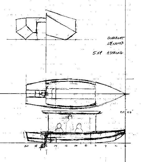
Well, you will need bulkheads in most boats to hold the boat in its shape and to divide it into various compartments and to provide structure for introducing loads from motors and sail rigs, etc. A canoe or rowing boat often needs none. Bob wanted an open compartment in the bow for the anchor and junk, and a wide open center cockpit for lounging, and then a motor hung on the aft part of that cockpit for easy access to the motor. That is he did not want the motor way on the stern. Phil Bolger has said over and over that a motor "well" inside the stern of a boat is a terrible thing, his opinion based on personal experience. So my idea with Bobsboat is to place the motor in a slot which is open to the stern and hopefully this will eliminate the badness of fumes and the well "pumping up" with water at speed. We shall see. So I'm placing the bulkheads like this:
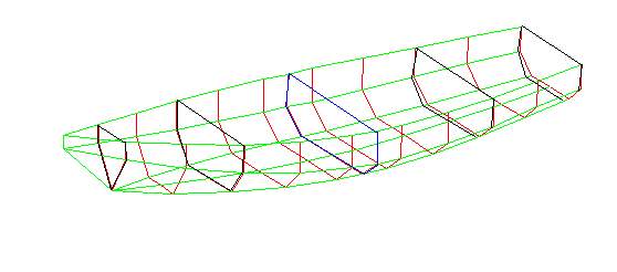
One other factor in placing these is to maintain the shape of the hull as it is being assembled. I have found that a spacing of about 3' is about the best and since the bulkheads are often farther apart than that the use of forms in between to hold the hull shape is a good idea. On Bobsboat I would take a chance that the 5' spacing in the cockpit area will be OK. On a boat with plumb sides like this one it can work. On a boat with flared sides you have to watch your hull assembly shape pretty closely since if it droops in one way or another as you assemble it you can vary quite a bit from the planned shape. When I built my Birdwatcher a long time back the spacing on bulkheads was over 6' and with the 1/4" plywood sides on a 24' hull you could easily push the assembly ends up and down a foot before the wales and chine logs were added. (By the way, from that experience you will find I always add the wales and chine logs at the earliest possible time in the boat's assembly.)
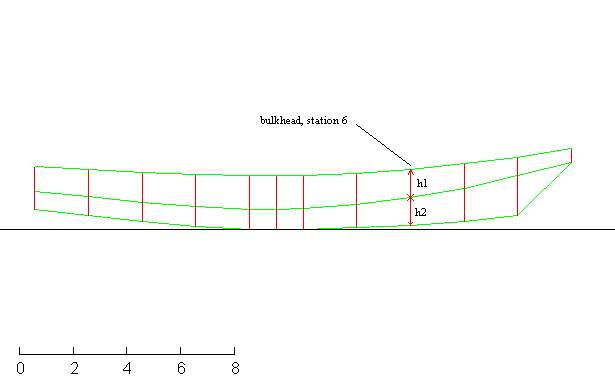
How to determine the shape of the bulkheads? We will start with a real easy one, say the bulkhead at the front of the cockpit at station 5. Pretty simple. If you look at the side view at station 6 you can measure off the length between the bottom and the chine, and then the length between the chine and the sheer.
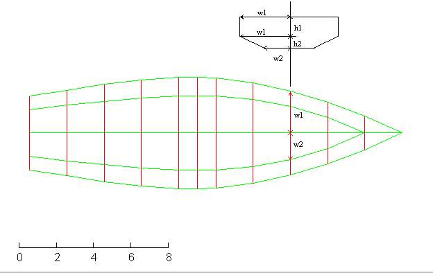
Then from the top view at station 6 you will get the width at the sheer and the chine (they are the same on this plumb sided boat) and the width of the bottom. Then draw them out like this:
Tilted bulkheads and raked transoms are a bit more challenging but still pretty simple. Let's take the bulkhead at the end of the cockpit which is to be tilted 15 degrees to allow the mounting of the motor (outboard motors are made to mount at 15 degrees with very few exceptions). Draw the bulkhead on the side view like this:
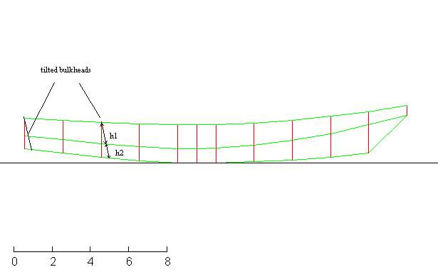
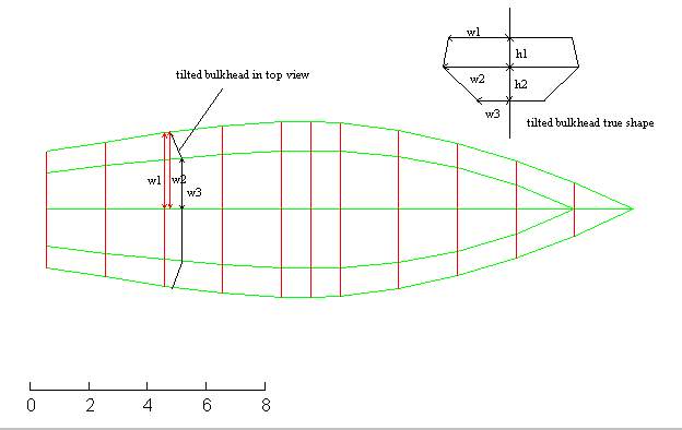
Now you can measure the distances from the bottom to chine and from the chine to sheer as shown and find the true depth of the tilted bulkhead. Also you need to project to the top view where the chine and bottom will intersect the bulkhead. Then from the top view you can get the widths of the bulkhead at the sheer, at the chine (no longer the same as the sheer width since this bulkhead is not plumb) and bottom. Then you can get the true shape of the tilted bulkhead by laying these all out like this:
ON TO THE SHAPES OF THE SIDES...
To get the true flat shape of the side panels you need to think in terms of peeling them off the boat and laying them flat. To do that you always need to draw a view of the boat that will show the proposed panel on edge. In our example let's use the top view to see the side panels on edge. (The side view shows the bottom panel on edge.) Here is how I used to do it. First get the edge view. Then "tick" the edge view at regular intervals, say every 12" in this case, like this:
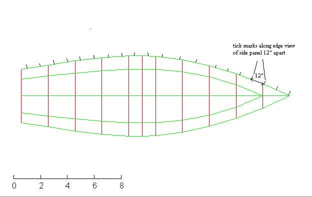
Note that your tick marks won't lie on top of the regular stations, the more the sides curve the farther the ticks will vary from the station marks as you tick from bow to stern. On a typical 15' hull you might expect the 15th tick mark to be 3" or 6" short of station 15.
Project those tick marks down to the side view. You can define the panel shape at each tick mark now by measuring up from the base line to what will be the chine edge and the sheer edge of the side panel. Like this:
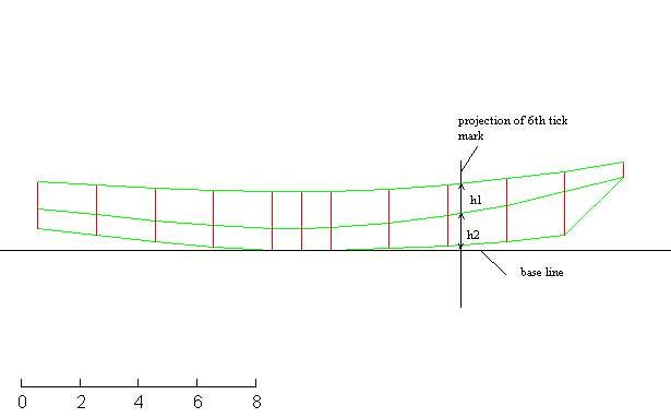
Now you can begin the flat panel layout of the side panel by starting with a new piece of paper and laying out those tick lines on the flat, that is drawn 12" apart intesecting the base line. Then reconstruct those chine and sheer dimensions at each tick line like this:
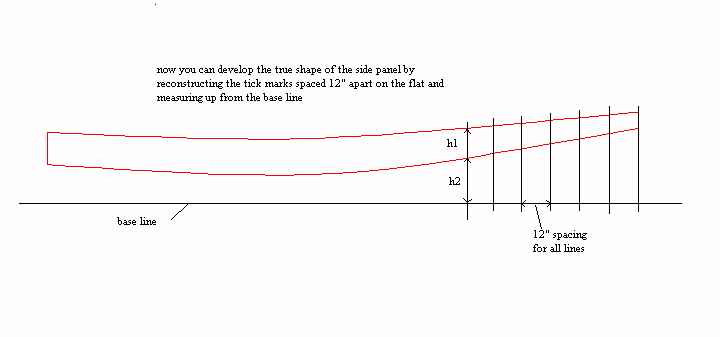
Do the bottom in the same way.
Scale the pieces on real plywood, cut them all out, and stick them together and you will have the beginnings of your real boat. You will have a big hole where the chine panels fit but you will be able to lay a piece of plywood over that hole and scribe the panel to shape, cut it out and fit it in. That is how I drew the original Toto plans and on some of my earlier multichine plans like Mixer and Woobo I don't give the bilge panel shape but simply ask you to cut the panel to fit the assembly. Got me off the hook back then and to tell you the truth you should always trial fit the bilge panels before cutting to the line since they are always the last piece of the hull puzzle to go into position and will collect all the errors, both mine and yours, of the total assembly.
THOSE BILGE PANELS...
If the bilge panels are not twisted then you can do the same procedure as above to predetermine their shape. You will need to draw a new view of the boat so you can look at that panel on edge. You will have to do the same if you have drawn a boat with flared sides.
But if the panels are twisted, then you will not be able to draw a view of that panel on edge. It can't be done this way. There have been lots of "twisted" drafting methods tried in the past to conquer this problem, none of them easy or especially accurate. (I should add that being able to do this sort of drafting really separates the men from the boys and may be a lost art. Draftsmen could wrap panels at all angles, cones intersecting flats and cylinders and then back to cones. I saw a design on Phil Bolger's drawing board a long time ago and not only were his panels not plumb, his section lines weren't either. I suspect he started doing "box boats" just to clear his mind.)
What is done today is to lay out the hull in a digital manner and we will pick this up in the next Bobsboat issue. The technique is so powerful that there is really no need to unwrap even simple side and bottom panels with the above method. Your PC, given the proper spreadsheet, can do it faster and with much greater accuracy.
NEXT TIME...
We'll rerun the bulkhead bevel essay.
River Runner
RIVER RUNNER, FLOAT BOAT, 15-1/2' X 45" X 100 POUNDS

This was a custom project for a man who wanted a Lowe Paddlejon boat but found they were quite rare, essentially a custom order. The idea of a boat like this is to float mild rivers with a guide in the stern directing with a paddle and a passenger or two up front fishing. You might recall the design I did last year called Ozarkian which is very similar, maybe the father or grandfather of the Lowe design. (I suspect southern Missouri is sort of jonboat heaven, the source of most of them both in spirit and in material. I recall driving the interstate down to Springfield, Mo. about ten years ago and near Lebanon, Mo I passed what seemed to be miles of aluminum jonboats and pontoon boats stored in fields along the highway. Even little children there must know how to weld aluminum.)
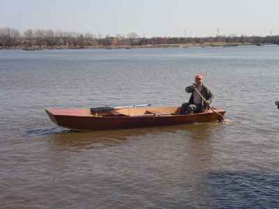
He sent me some photos of a paddlejon he had seen recently and a sales brochure. I tried to copy the lines, thinking all the time that these boats are a lot more subtle than you might think. At the time I had no real Lowe around to study but the brochure left me with the impression that the paddlejon was perhaps a regular small power jon made long and double ended with swept up lines both fore and aft to allow easier paddling. But it is not quite a true double ender in that the stern transom is raked for the usual 15 degree motor mount. As far as power goes, a boat like this won't plane nicely at all, trying to stand on its stern at the least excuse, so I say 3 hp max.

Getting back to the lines, I had the feeling that these are made from a constant width piece of aluminum, say 32" wide on the bottom and 16" wide for each side for a total panel width of about 64". Stiffening wales are already pressed into the panel. The flat wide panels are folded with a brake such that the proper flare of the sides is established. The end chines are notched and the end bottoms drawn up and the end sides are drawn in to close the notches which are then welded shut. But the chines for the main portion of the hull are not welded at all, just bent. There seems to be another trick in that the top of the sides bends inward a lot sooner than does the bottom of the sides, resulting in a rolling flare that gives the boat a somewhat elegant shape (I think). So you might think a manufactured jonboat is a dumb and brutish thing, but I'm quite certain most of them are actually pretty clever.
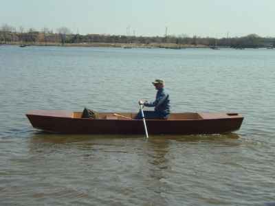
Jim Hauer built the prototype in Green Bay and sent these photos. I think it came out exactly as hoped. Remember, this is not really a rowing boat as much as a floating boat so the face forward rowing will be used more to steer than to propel. The photo of the man paddling in the stern shows that the aft transom is still up giving good flow lines there, unlike a square stern power jonboat. Under power Jim said that 2.5 hp is about all you can take, the boat not behaving well above that.
Anyway, River Runner uses five sheets of 1/4" plywood. The idea of the light ply is to keep the boat light enough to manhandle into a truck or onto a car roof but it will take a diligent builder to keep it light. I suspect the aluminum original would be no heavier. Simple nail and glue construction.
River Runner plans are $20 when ordered direct by mail from me.
Prototype News
Some of you may know that in addition to the one buck catalog which now contains 20 "done" boats, I offer another catalog of 20 unbuilt prototypes. The buck catalog has on its last page a list and brief description of the boats currently in the Catalog of Prototypes. That catalog also contains some articles that I wrote for Messing About In Boats and Boatbuilder magazines. The Catalog of Prototypes costs $3. The both together amount to 50 pages for $4, an offer you may have seen in Woodenboat ads. Payment must be in US funds. The banks here won't accept anything else. (I've got a little stash of foreign currency that I can admire but not spend.) I'm way too small for credit cards.
The AF4G is done and launched. Writeup after testing:
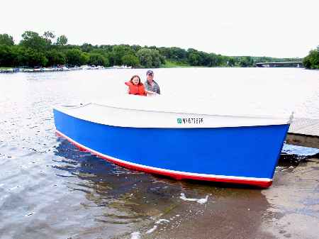
Garth has the big Cormorant project to the point where he can run power to it and set it up with a mattress and TV set and Mr Coffee and make it a hangout for the New York winter!
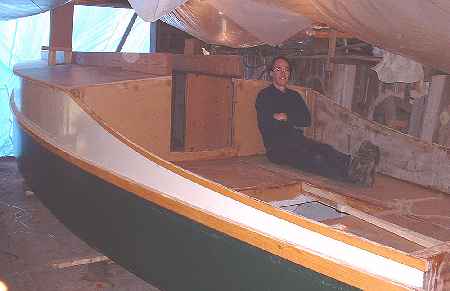
The out West Picara has its roof and some major sail rig bits done:
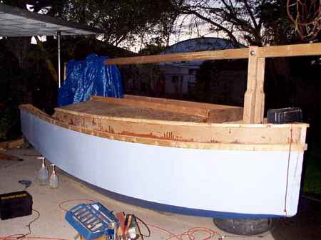
The down South Picara is getting its innards done.
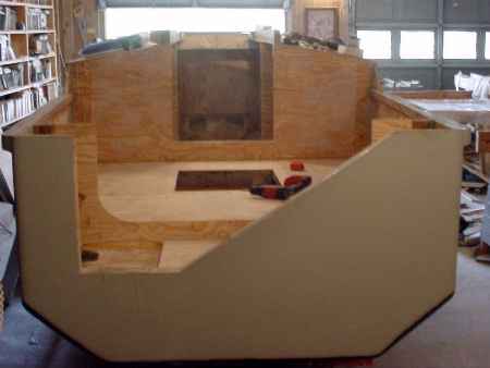
This long and lean project is a 19' version of Toon2. I don't have the drawings done yet. The builder is working from preliminary drawings and is about to pass me up. MDO plywood looks like cardboard now but it isn't.
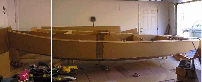
We have an experienced builder starting a Mayfly16:
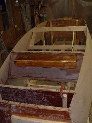
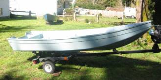
This is a slightly modified Veep14. I'm told the sheer is raised a bit and the stern given a bit of flare but the bottom is per the plans. Waiting for a test:
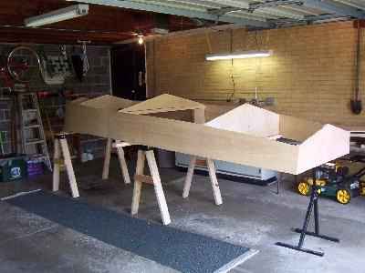
And here is the beginning of a Vector. The builder is keeping a website of the project at http://www.geocities.com/michsand@sbcglobal.net/
AN INDEX OF PAST ISSUES
Hullforms Download (archived copy)
Plyboats Demo Download (archived copy)
Brokeboats (archived copy)
Brian builds Roar2 (archived copy)
Herb builds AF3 (archived copy)
Herb builds RB42 (archived copy)