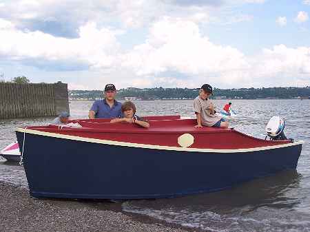
Fred Shooner & Co. launch his new AF4 in Quebec.
Contents:
Contact info:
Jim Michalak
118 E Randall,
Lebanon, IL 62254Send $1 for info on 20 boats.
Jim Michalak's Boat Designs
118 E Randall, Lebanon, IL 62254
A page of boat designs and essays.
(1Aug05) This issue will figure some of Bobsboat's bevels. The 15 August issue will rerun the taped seam essay.
THE BOOK IS OUT!
BOATBUILDING FOR BEGINNERS (AND BEYOND)
is out now, written by me and edited by Garth Battista of Breakaway Books. You might find it at your bookstore. If not check it out at the....ON LINE CATALOG OF MY PLANS...
...which can now be found at Duckworks Magazine. You order with a shopping cart set up and pay with credit cards or by Paypal. Then Duckworks sends me an email about the order and then I send the plans right from me to you.

|
Left:
Fred Shooner & Co. launch his new AF4 in Quebec. |
|
|
Bobsboat Bevels 8
In the last Bobsboat issue we made a cardboard model using the panel expansions developed in the episode before that. If this were to be a totally taped seam construction we could start drawing the construction drawing right now. But the way I have done taped seam boats is to attached beveled sticks to the bulkheads and transom and the stem, at least to the point where the boat can be solidly assembled initially with traditional nail or screw and glue construction. Then the builder can scope his boat out well enough before he dips his hands into noxious materials. Actually with this method a fellow can start his project, take it apart and move it, and put it back together.
So how to figure the bevels needed to preassemble the bulkheads, etc.?
First, The Very Basics....
The only way to see the true bevel of a joint between two panels is to arrange the view on your drawing board such that you see both panels in edge view. For example:
The First No Brainer...
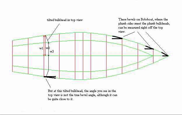
If you have a plumb sided design like Bobsboat, your top view will often suffice to get nearly all of the bevels required. You will be looking straight down the plumb sides in the top view and if your bulkheads, etc. are also plumb, you are seeing it right. Just take a protractor and measure the bevels right off the top view, like this:
. 
What if you have a boat with sides that are flared but not twisted, like many flatiron skiffs? You have to draw another view tilted so you are looking straight down the side.
I've got a little hint that I have found to save a lot of extra view drawing: if the amount of flare is small, say 5 degrees, the bevels are essentially what you see in the normal top view.
Also, if your panels are twisted your bevels will twist with them - a rolling bevel. You won't be able to predefine a bevel although you might get it close enough to get started with construction and then roll the bevel on the job site.
Raked Stem Bevels...
If your sides are flared and have no twist then you will have a raked stem. You can't just measure this one from the top view. Here is a guide of one way to do it.
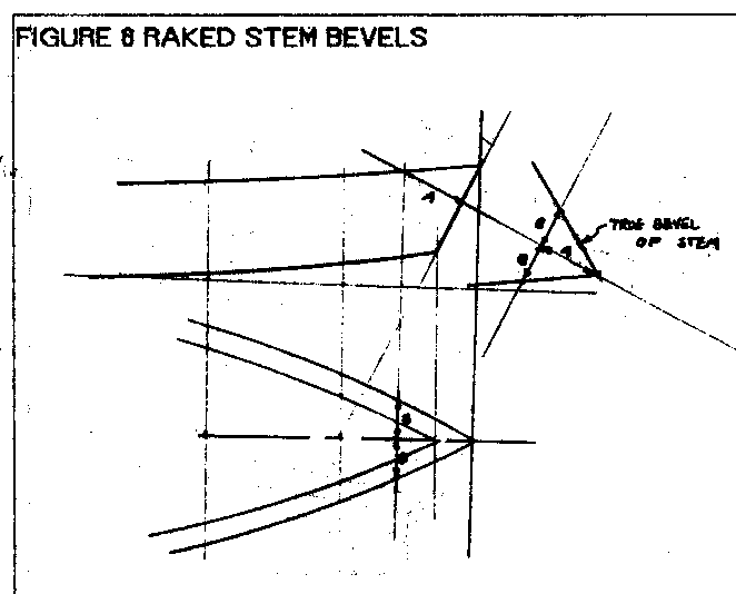
Remember that you need to twist your view such that you are looking straight down the stem.
Tilted Transoms:
On Bobsboat and on many boats the transom here (and the bulkhead in front of it) are tilted 15 degrees. On Bobsboat that is for looks but on almost any boat that will mount an outboard that 15 degree tilt is standard. It is what almost any outboard is designed for. So a simple look at the top view, or any view that simply looks straight down the sides, won't be enough.
No Brainer Number 2...
Grab that card model you made last time. Find the intersection of the panels in question, in this case where the side meets the transom. Mark lines on both joining panels that are perpendicular to that joint. Now cut a template that fits exactly at those lines. Like this;
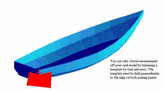
Now use your protractor to measure that angle. You might check the opposite side with the same template. With a small flimsy card model this method is not too exact but then again it requires no computer or twisted thinking so your answer will be pretty close. While you are at it you might double check the stem bevel you calculated with the same model.
Next, twisted thinking...
The required bevel can be determined on the conventional drawing board. Here are the basics:
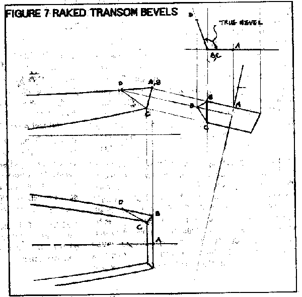
Essentially here you start by making a true shape projection of the transom. Then you make another projection that looks straight down the edge of the transom as shown. These can be done in a jiffy if you are practiced but if you are just drawing a boat every now and then, you might have to go slowly and carefully. Then you ought to check it against the No Brainer Number 2 results. It is easy to twist your thinking the wrong way!
Now For True Rocket Science!!!
Look at this view of the Bobsboat and note that I have constructed two triangles, one on the side and one on the transom and they share a common edge. We want to find the angle between those two triangles and that is the mystery bevel.
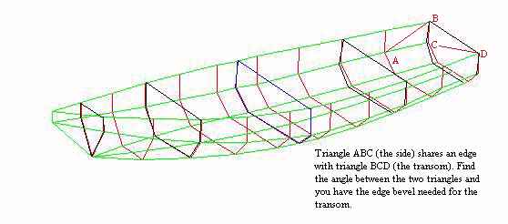
Remember we have already drawn the lines and taken offsets at regular points. So we can look quickly at our drawing and see the xyz dimensions of the points. So only four points in xyz space are needed here to define both joining triangles since they share two common points.
Hope you paid attention to your university math! You may think that 100% of that stuff was useless in real life but I can assure you that about 25 years after I graduated I found 1% that I needed.
Take triangle ABC. The plane that triangle lies in (which is really the plywood panel) can be defined by two joining vectors, vector AB and vector BC. If you take the CROSS PRODUCT of those two vectors you will get a third vector that is perpendicular to the plane of triangle ABC and can be thought of as the "direction" of that plane.
Similarly with triangle BCD. Take another cross product and find its direction vector.
Now if you take the DOT PRODUCT of those two vectors you will get a number that represents the cosine of the angle between the two planes! And from there you can figure what the angle between the two planes is. There you have it - the mystery transom bevel.
Now don't ask me how to figure cross products and dot products. This is vector math involving matrices of numbers and is true rocket science. But you can dig them out of those old math books you probably threw out. In the mid 60's when I was in school we used to beat these numbers to death with a Pickett slide rule and a lot of pencils and paper. If you had thirty kids in a class you would get thirty different answers to the problem given the errors in the endless calculations required. BUT NO MORE! Today you plow your way through it once with a spreadsheet in a PC. Then the machine does the calculation with no error in the time it takes to tap ENTER. My spreadsheet asks for the xyz offsets for the four points that define the two panels and then it spits out the needed bevel angle!
And then I always check the results against my card model just to be sure. Once your spreadsheet has been debugged it is usually faster to figure all of the boat's tilted bevels this way!
NEXT TIME...
We rerun the tape seam essay.
Polepunt
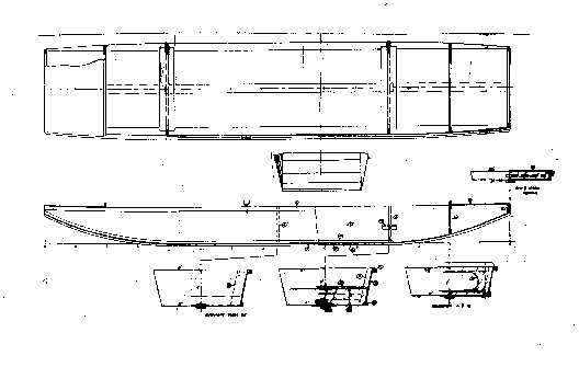
POLEPUNT, PUNT, 15' X 3', 110 POUNDS EMPTY
Do you have a swamp in your back yard? Turn that into a positive thing with a tradional punt that you push through the shallow water with a pole. I think this sort of boat has a long history and the similar shape in Chapelle's great book AMERICAN SMALL SAILING CRAFT goes back to at least the 1700's. Those weren't built of plywood, of course, and would be a lot heavier than this one. Actually Chapelle shows the shape of the old one as more elaborate than this one but I'm pretty sure this one is in no way harmed in function by the simplicity of its shape.
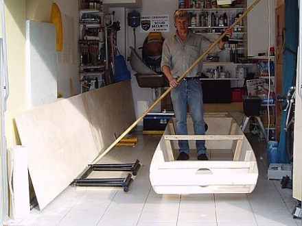
In particular I drew in a feature that I saw on a commercial aluminum jonboat. That is a constant width bottom. I used that feature on my Jonsboat design and it works very well. It might make the boat easier to build although something like Polepunt is easy to do in almost any case. I kept the bottom dead flat in the center 7' with no frames there so that you might walk the center as you push the pole. The boat is narrow at 30" inside on the bottom and I'm hoping that will make it stable enough to stand in. But such a light boat will be dominated by your weight and you will need to be careful how you stand. I've also shown rowlock sockets on the drawing and this might suit as a rowing boat using a removable seat. And this might be very suitable for floating streams with paddles, a substitute for an aluminum canoe. I see no good way to use a motor on a boat like this. The ends (which are identical) are swept way upward for good lines at slow speed and won't support any weight fore and aft. The only chance for a motor would be with an electric with remote steering so yo can keep your weight forward for proper trim. I've written words like that for almost all my arm powered boats and I still get regular photos of those boats with motor plates mounted on the stern. But I never get photos of those boats under power most likely because the owner tried it just once and never again after it tried to stand on its stern when the motor was fired up. So if you want power, and there is nothing wrong with that, build Jonsboat instead.
Anyway, our old buddy in Poland, Wojtek Baginski, built the prototype to perfection. In one of Phil Bolger's books he says the real trick of designing a successful boat is to get your design into the hands of the right user, and so it is with Wojtek. Here is his account of the maiden voyage:
"Here is a brief description of polepunt nautical characteristics. The first is that polepunt is incredibly stable. During our cruise the crew (Wojtek Baginski is in the stern in most of these photos and his boating buddy Wojtek Holnicki in the bow) was often forced to gather on the stern first, and next on the bow (after boat's center has passed over the bar) to jump over a tree or a branch laying in the water, not stopping the punt. We were using the internal stiffener as a walkway and it helped much to keep the balance.
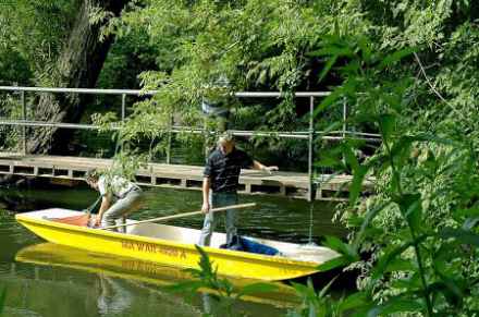
The second notice is that polepunt responds to oar action very well. After more of less a strong push of a pair of paddles she smoothly went a long distance on calm water. Looks like rowing will be successful as well, when an oarsman will take a seat at the center of the boat, and will pull the boat with the pair of 7 foot oars (we have chosen a pair of heavy ones for the Vistula , because of possible wind and waves acting on her open area against the boat). As for using a pole, it's really amazing and effective power, but needs a bit of experience. Worth learning!

Another notice is that the boat is surprisely strong, I think because of relatively low ratio of free plywood surface to chine logs, stiffeners, gunwales and frames. She got a few strong hits and scrapes from wooden, concrete and stone objects, but generally everything is OK, external chine logs gave good protection to the sides in extremal conditions. I laminated the bottom with a fiberglass twice, inside and outside, by the way.

So, the boat is really useful in various conditions (we checked her out during 20 km long raft in various water areas including wild state creek, regulated state creek, small man made lagoon and big river). I think with her low cost and quick building process she is a very good proposition not only for beginners but for advanced adventurers as well (hey don't look at me! :).
Thanks Jim."

Thank YOU, Wojtek!
I want to point out here is that a stream like this clearly isn't meant for modern boats and if you have a boat like Polepunt you can navigate it and pretty much have it all to yourself. This can be really high quality boating.
Nothing to builiding Polepunt, of course. Nail and glue construction from four sheets of 1/4" plywood.
Plans for Polepunt are $20 when ordered directly from me.
Prototype News
Some of you may know that in addition to the one buck catalog which now contains 20 "done" boats, I offer another catalog of 20 unbuilt prototypes. The buck catalog has on its last page a list and brief description of the boats currently in the Catalog of Prototypes. That catalog also contains some articles that I wrote for Messing About In Boats and Boatbuilder magazines. The Catalog of Prototypes costs $3. The both together amount to 50 pages for $4, an offer you may have seen in Woodenboat ads. Payment must be in US funds. The banks here won't accept anything else. (I've got a little stash of foreign currency that I can admire but not spend.) I'm way too small for credit cards.
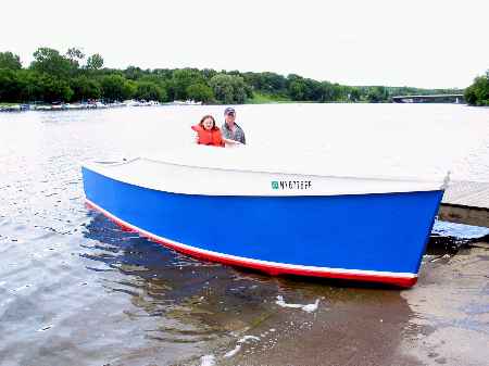
The AF4G is done and launched. Writeup after testing:
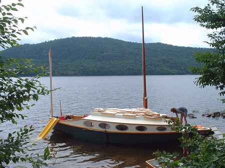
Garth has the big Cormorant done and has spent a family vacation with it. Report next issue:
The out West Picara has its roof and some major sail rig bits done:
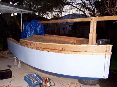
The down South Picara is getting its innards done.
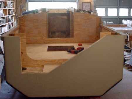
This long and lean project is a 19' version of Toon2. I'm told this one is more or less complete, left with the 15 % of the work that takes 85% of the time.
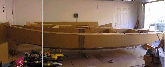
This is a slightly modified Veep14. I'm told the sheer is raised a bit and the stern given a bit of flare but the bottom is per the plans. Waiting for a test:
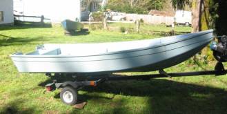
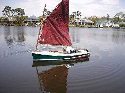
A Vector builder is keeping a website of the project at http://www.geocities.com/michsand@sbcglobal.net/ but in the meantime I got photos of a Vector completed by Pete Mohylsky in Florida. Here he is fussing with his sail. Hopefully a report soon:
AN INDEX OF PAST ISSUES
Hullforms Download (archived copy)
Plyboats Demo Download (archived copy)
Brokeboats (archived copy)
Brian builds Roar2 (archived copy)
Herb builds AF3 (archived copy)
Herb builds RB42 (archived copy)