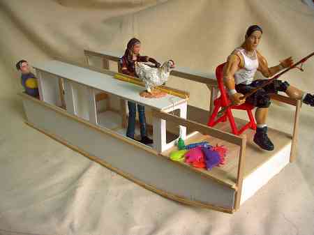
Mak Sui Shing is making models in Hong Kong. This is a model of Shanteuse fitted out as it should be.
Contents:
Contact info:
Jim Michalak
118 E Randall,
Lebanon, IL 62254Send $1 for info on 20 boats.
Jim Michalak's Boat Designs
118 E Randall, Lebanon, IL 62254
A page of boat designs and essays.
(1jan07) This issue will rerun that September 2003 article where I measure prop thrust. Next month we will jump back to guestimating hull drag.
THE BOOK IS OUT!
BOATBUILDING FOR BEGINNERS (AND BEYOND)
is out now, written by me and edited by Garth Battista of Breakaway Books. You might find it at your bookstore. If not check it out at the....ON LINE CATALOG OF MY PLANS...
...which can now be found at Duckworks Magazine. You order with a shopping cart set up and pay with credit cards or by Paypal. Then Duckworks sends me an email about the order and then I send the plans right from me to you.
Measuring Prop Thrust
"THE MOST SIGNIFICANT NEGATIVE EXPERIMENT IN THE HISTORY OF SCIENCE"!!!
Before I get started talking about propeller thrust I want to set the stage with a dedication to Albert Michelson who spent his life measuring the speed of light. Born in Poland, his family came to the US when he was a little boy. He became expert with optics. In the mid 1800's the speed of light was known in a general way and Michelson, along with his helper Morely, made a device that would measure the speed of light to a degree of accuracy never known before. In fact they thought it so fine as to measure the effect of the earth's orbital movement on the speed of light according to the "ether" theory of light propogation that was current at that time. So they measured and measured and measured. They did indeed zero in on the speed of light but saw no orbit effects. The speed of light was the same no matter how it was measured. Michelson had enough confidence in himself that he published the results even though there was no explanation to be had. That was in 1883. Then in 1905 along comes young Albert Einstein who knows about Michelson's results. Einstein doesn't really explain it except maybe to say "accept it because that is the way it has been proven. The speed of light is always the same no matter how you measure it." And with that basis Einstein went on to figure his theory of relativitly and the rest is history. So just because you can't explain something you measured doesn't mean it is wrong.
NEXT...
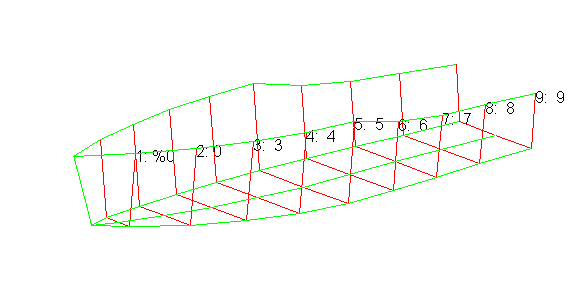
Some of you may recall that I've noted on several occasions the virtues of the program Hullforms. You can link to the Hullforms website in the links at the bottom of my page and download a free trial version. In one of the later trials there is an option that will figure (somehow) a drag vs speed chart for your hull given a certain weight and trim. I don't know how it is figured. In fact I'm not too sure the Hullforms writer took the results all that seriously since he presents several curves using the equations of several professors, and since he didn't put grid lines on his charts leaving you to think they are probably quite approximate. This is not an instantaneous program. You must "model" your boat first by plugging in the offsets that define its shape and you need to tell it the weight and center of gravity information. Anyway, here is a picture of my Hullforms AF4 model.
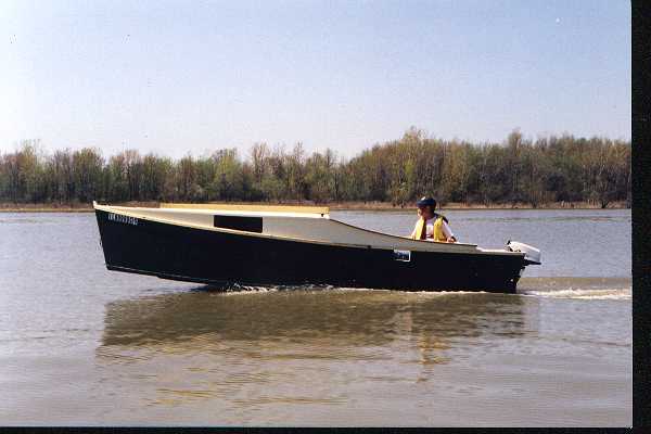
My real AF4 looks like this (back a few years ago when both the boat and I were younger and lighter)...
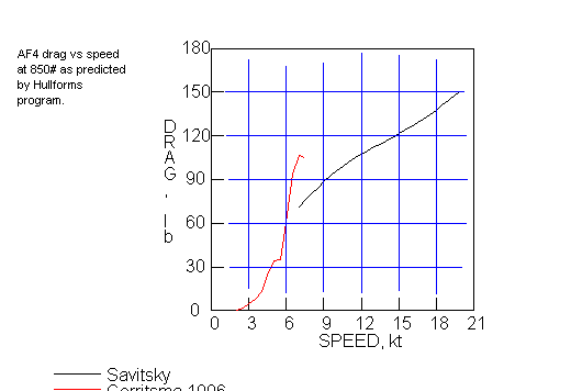
The Hullforms program predicts for this model, at a full weight of 800 pounds (about real life) and a cg location 11' aft of the stem, this drag vs speed chart (I've added grid lines to make guessing easier).
Well now, if such a chart is accurate can Hullforms be used to predict the performance of a boat given a certain weight and trim and power??
PROPELLOR THRUST....
... seems to be something that no one wants to talk about (except trolling motor guys who refuse to talk about horse power). All gas outboards are measured in horsepower. Sometimes someone will tie his boat to a tree and measure the static thrust of the motor, but is that an indication of thrust at speed? The thrust of an aircraft propeller is said to decrease with speed and the thrust of an aircraft jet increases greatly with speed so knowing the static thrust may not be much of a help in predicting thrust at speed.
You might recall in the "horsepower" essay from a few issues ago that horsepower is basically speed times a load. Hey! That chart above is speed times a drag so it can be used to figure the horsepower pushing the boat. Does it work? Let's take an example. It is known that in real life my 15 hp motor will push my AF4 at about 18mph tops. But when I look at the Hullforms chart I see that at 18 (about 15.6 knots) mph the hull will have about 120 pounds of drag. 18 mph is 1600 feet per minute so the speed times the load is 190,000 pounds - fpm. A horsepower is defined as 33,000 pounds - fpm so the chart predicts 5.8 horsepower needed to get 18 mph on the AF4! Not much agreement there.
SO I MAKE A THRUSTOMETER...
I tried to think of ways to measure the thrust at the prop as the boat was underway. If I were a true tinkerer's mechanic I think I would try something like this: the motor mounts on a transom bracket that is hinged at the top and has a "load cell" sort of thing on the bottom. I thought that might be a small hydraulic cylinder more or less like an auto's brake cylinder with a pipe that leads to a pressure dial on the dash. As the motor pushes forward at the prop the cylinder gets pinched against the transom which is resisted by the oil inside with increased pressure. Read the pressure in the cylinder with the gauge and you can figure out the total force on the cylinder and from there you can figure the thrust at the prop. This could be a permanent thing although I've never heard of it being done.
Not being a true tinkerer I settled on a method that relied on 2x4's, duct tape and a bathroom scale. Here is a photo of my Thrustometer.
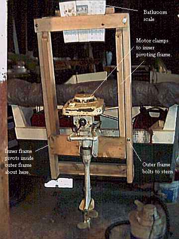
The outer frame of the thing bolts to the real transom. The inner frame which has the motor mount is pivoted inside the outer frame. As the propeller thrusts forward the inner frame wants to swing its top aft. In doing so it pinches an ordinary bathroom scale which you can read very easily. The scale does not read the prop thrust as 1 to 1. Since the motor mount pivot is about 20" from the prop thrust line and the scale is about 33" above the pivot, the actual thrust at the prop is about 1.65 times the scale reading.
This bolts to the transom with two small bolts. I don't think it will take for very long the stresses of trailering so I mount it on the hull after the boat has been launched. Also the thrustometer is not braced in any way to take reverse thrust of the motor so that is a no no. I tried to keep the motor mount as close to the real transom as possible so that the motor geometry would be as close to the real use geometry as possible. I thought the limiting factor here would be the motor's clamping handles and I left just enough space for them. But in use I found I can't tilt the motor forward with the thrustometer so care is needed that way in addition to not being able to use reverse. Plan ahead.
DOES IT REALLY WORK?????
These bathroom scales are wonderful things and I must take one apart sometime to see what makes it tick. This one cost $3 at Dollar General. When I hang a motor on the Thrustometer it's weight alone puts pressure on the scale. No problem since the scale has a wheel to zero that out so all tests start with zero.
First testing was done with a 1956 Montgomery Wards 12, a Gale made motor that is essentially an OMC. I could tell the moment I popped it into fwd that the Thrustometer was OK. Testing actually only takes a few minutes using a gps. Starting from idle in fwd let the motor and boat settle to a certain throttle setting and write down the speed and scale reading. Increase throttle to a new speed and so forth right up to full throttle. Afterward figure the prop thrust using the 33/20 factor of the Thrustometer's geometry and that is the prop thrust, right?
In detail I don't think it really is the prop thrust because the drag of the lower unit never gets into the system. The lower unit drag I think cancels itself out and never gets measured. So the prop thrust is no doubt actually greater than what I am measuring. BUT THAT IS GOOD! I think what is really being measured here is the thrust actually pushing the boat forward. It is the force that counteracts the drag predicted by the Hullforms chart!
Also I think that in detail the Thrustometer seems to slow the boat down about 1mph. At least with the two engines I used I got that result both times. It could be the extra weight in the stern, something AF4 has never cared for. Also I noticed a lot of splashing going on back there that is not present usually. The Thrustometer mounts totally above the bottom of the hull so I don't really know what the splash is about.
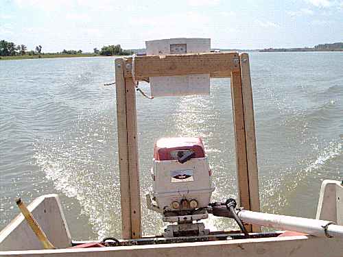
Here is a photo of the Thrustometer in action with a Montgomery Ward's 15 mounted (another Gale OMC motor from about 1960).
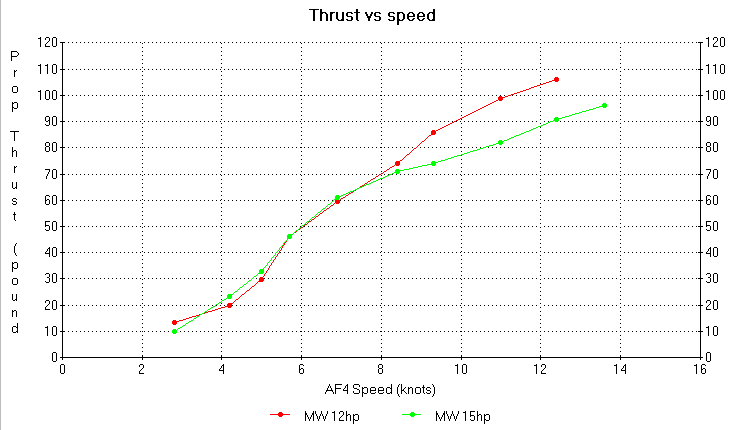
I plotted the results of the two motor tests and got this:
Here is a chart of the testing results on top of the original Hullforms prediction.
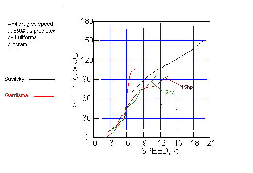
I thought they matched pretty well all things considered. The big "hump" predicted by the low speed professor never happened with my AF4 even though I went looking for it with several test runs in that speed range. Perhaps if you are properly prepared you really can use the Hullforms charts to predict speed for new hulls or effects of weight and trim.
Note that the MW12 and MW15 lines don't agree above "hull speed". (They were for all purposes identical up to that speed.) I think they should agree and can't think of any reason why they don't. I thought when I did the MW15 tests that the Thrustometer might have been binding somewhere to give the odd results but I ran that motor a second time with the same results. To be sure I gripped the Thrustometer together with my hands which sprung the scale beyond the range of the test and it bounced right back to zero freely when I released pressure.
Secondly it is interesting to wonder where all the horsepower goes. Only about 30% of the rated power is used to push the boat forward.
So I'm waiting for an Einstein to show up to explain it....
NEXT TIME...
We'll rerun that old prop thrust article.
LFH17
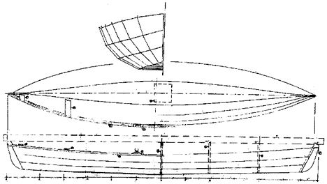
FAST ROWBOAT, 17' X 3.5', 100 POUNDS EMPTY
Don't remember where I read this but 100 years ago rowing was all the rage, the sort of thing you did on for fun. They said its popularity dropped and died after the invention of the modern "safety" bicycle which replaced it for athletic recreation. The Herreshoffs in Rhode Island had a historic boat business going at that time making everything from huge racing yachts to dinks to torpedo boats. L. Francis Herreshoff carried on the tradition in the 1900's being a great designer, artist and writer and educator. I suspect anything he wrote is worth seeking out. I have a copy of his book SENSIBLE CRUISING DESIGNS which I think is a compilation of articles he wrote for THE RUDDER magazine about 50 years ago. Lots of really good stuff in there. Among it is a discussion of good rowing boats with a "cartoon" presentation of a 17' rowing boat that would be fast and able but also simple and comfortable and not extreme. John Gardiner, another legend in small boats whose writings you should seek out, elaborated on that LFH cartoon and presented offsets for his idea of that boat in his BUILDING SMALL CLASSIC CRAFT, VOLUME 2. Both L. Francis and Gardner were used to traditional lapstake construction and thought nothing of presenting such a design. But the special lumber and tools needed for lapstrake are not common at least where I live. So I got an order for the LFH design redone for taped seam plywood. Thus the design I call the LFH17. As with L. Francis' original the LHF17 has a narrow flat bottom making it a dory of sorts and is identical bow and stern
This boat will be a bit more complicated to build that most "instant" boats, I'm quite sure. For one thing it has three panels on each side to keep track of. And since they are long narrow pieces, all with a lot of flare, I doubt that it will jig itself like boats with wide plumb sides. So even though I show the expanded shapes of the individual planks I've also shown it made on a backbone or ladder frame so that it can be kept in proper alignment as it goes together. And, as with the original which probably had six or so strakes to each side instead of the three I show, the bottom bilge panel or garboard twists about fifty degrees in its journey from mid boat to stem and I would expect a fair amount of pushing and shoving required.
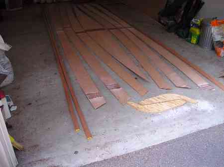
As you may know two prototypes were under construction. One by John Trussel in S. Carolina, was built on the frame I show in the plans. Here is a photo of his basic parts:
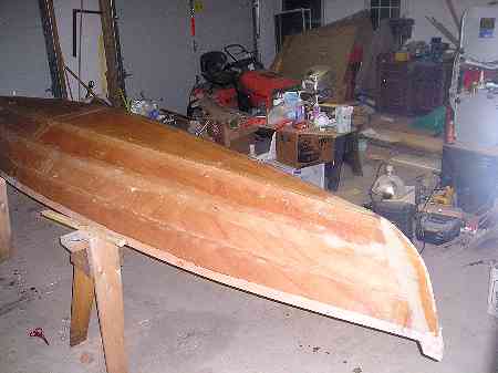
And here is a photo of his assembled boat. John said the building was at the limits of "instant" assembly and said he had to trim some of the ends of the planks to get them to fit easily. As I am writing this he has not yet launched the boat.
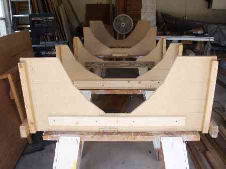
As John was building I heard from Doug Thomas in Florida who was building on a frame but his molds were females with the planks to be forced down inside, like this:
Doug did not trim anything but used lots of force to get the ends of the planks to fit, like this:
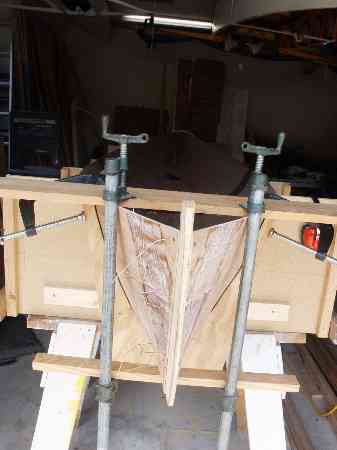
So maybe there is something fishy with my panel expansions.
Doug launched first:
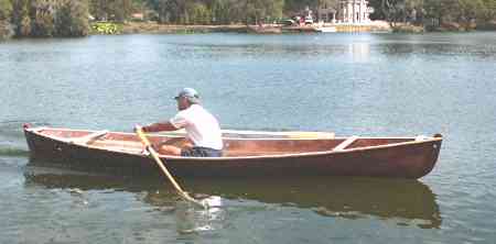
Doug wrote: "My LFH17 is not yet done, but it is functional. I couldnt resist trying it out once I had the oarlock sockets in. I had to have an on-the-water test to find the right spot for the foot braces, right?
I rowed it for 45 minutes last Wednesday. As expected, given the narrow waterline, it feels tippy getting in. However, once seated, one feels quite secure. There is noticeable flex to the hull when carrying it or when walking in the boat with hands on gunwales. There is no noticeable flex when rowing though. It might get a temporary thwart to make it easier to carry. Built in 5 mm Luan, it is light enough to carry but is a bit awkward due to the width.
The hull form seems to me a good compromise between tracking and maneuverability. It will track well enough if one pays attention. It can be turned readily. Todays outing turned up a tendency to round up into the wind however. Theres not much wake and it carries well between strokes.
I averaged 4.3 mph with 7.5 spoon blade oars, for a 3-mile outing. I have also tried 8 spoons and 8.5 Culler type blades. The 8.5s are too long with hands overlapping on the pull. Eight feet is about right for me, but the 7.5 work well too.
I am using the Gaco gated oarlock. See their Website. West Marine used to carry these, but I think they have discontinued them. This is the geometry that Phil Bolger prefers with the pin in front of the oar. This lock pivots on the pin, rather than the pin pivoting in the socket, so there should be less wear in the sockets. I am experimenting with just a 3/8 hole through the 1 oak riser block, gunwale, and a ½ backing block as the oarlock socket. I will probably make some oars with flats on the looms to match the flats on these locks. I am used to that configuration from all of my sliding seat rowing.
I left the hull in the female forms while I installed the gunwales and cross braces. I had to trim the form tops away from the boat to make room for the gunwale installation. It would have been better to plan ahead for this by making the molds shorter. Once the cross braces were in, I removed the screws holding the planks out to the molds and the planks relaxed only an eighth inch or so. I had to glass the exterior with the gunwales in the way, but this was not much trouble. I did elect to bevel the gunwale before installation. I cut it at 25 degrees. This is a bit of a compromise as the shearstrake angle varies a bit over the length. I planed the outer edge of the gunwale down to level in the ends in order to fit the cross braces. I added a third course to the gunwale for 2 in way of the oarlock sockets in order to replace some of the wood lost in the bevel and to get a touch wider oarlock spread.
I drilled 1 holes in the stems for the painter or for tying down while car-topping.
It occurred to me that the boat would set up fine for carrying a passenger if it just went backwards. This does away with the need for a second set of oarlock sockets. The only hitch is that the bottom board gets narrow where the seat goes. I made my rowing seat trapezoidal so that it would fit between the chines (10 and 12 bases and 12 fore and aft). I took my wife for a ride this morning and it worked well with her sitting a bit forward of the cross brace.
So far, I am quite happy with the boat. While at the boundary of the stitch and glue technique, it is not too hard to assemble. It is probably better done in glued lap, but that seems foreign to your customer base. "
Later he added:
"My LFH17 weighs 73 pounds in its current state, so hauling it around is roughly equivalent to carrying my 16 fiberglass canoe. It needs foot braces, a bit more epoxy, and paint yet. I used 5 mm Luan for planking, ¾ SYP ply stems, poplar for gunwales and cross braces, and oak for oarlock risers. There is not a lot of metal in it small screws for planking to stems, ring nails for the second course of the gunwale, and four screws in the oarlock risers. (I secured the first course of the gunwale with clamps and blocks notched 25 degrees to the face while the glue set.) The interior is epoxy coated and there is the epoxy filled 6-ounce glass over the entire exterior.
I think I will hold off on adding the skeg for tracking for now. I will get a bit more experience to see how much nuisance it is in varying cross winds before I add weight and drag.
The foot braces for rowing with a passenger fall near amidships. I am thinking of running them from the bottom plank to the gunwale in ½ ply and filleting them to all planks. This should stiffen up the sides. However, there will be only about 2 landing on the bottom board to leave room for the seat. This could make a nasty stress riser. "
LFH17 needs four sheets of 1/4" plywood with taped seam construction. LFH17 plans are $30.
Prototype News
Some of you may know that in addition to the one buck catalog which now contains 20 "done" boats, I offer another catalog of 20 unbuilt prototypes. The buck catalog has on its last page a list and brief description of the boats currently in the Catalog of Prototypes. That catalog also contains some articles that I wrote for Messing About In Boats and Boatbuilder magazines. The Catalog of Prototypes costs $3. The both together amount to 50 pages for $4, an offer you may have seen in Woodenboat ads. Payment must be in US funds. The banks here won't accept anything else. (I've got a little stash of foreign currency that I can admire but not spend.) I'm way too small for credit cards.
I think David Hahn's Out West Picara is the winner of the Picara race. Shown here on its first sail except there was no wind. Hopefully more later. (Not sure if a polytarp sail is suitable for a boat this heavy.
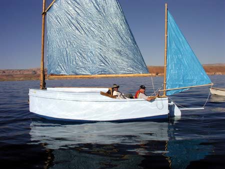
Here is a Musicbox2 I heard about through the grapevine.
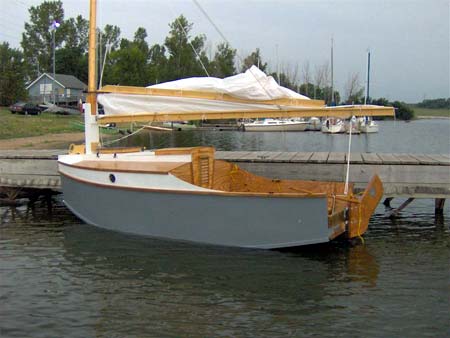
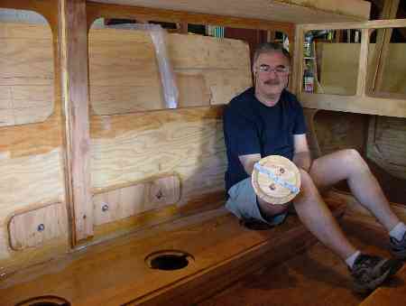
We have a Philsboat going together in California. You can see the interior room in this 15' boat:
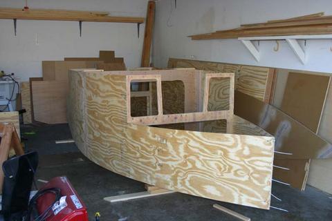
And here is another Philsboat in northern Illinois:
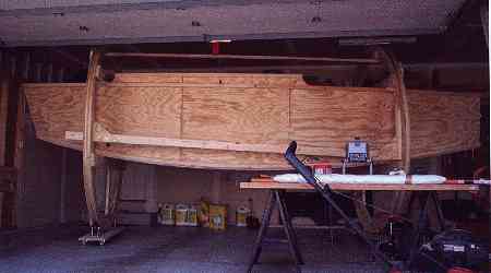
HOLY COW! A Jukebox2 takes shape in Minnesota. Unheated shop means no work during the winter. Check out that building rig!
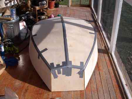
And the Vole in New York. Going very quickly but most likely there will be little more done during the cold winter.
Hullforms Download (archived copy)
Plyboats Demo Download (archived copy)
Brokeboats (archived copy)
Brian builds Roar2 (archived copy)
Herb builds AF3 (archived copy)
Herb builds RB42 (archived copy)