Contents
Beefing A Mast
I GOT AN INTERESTING QUESTION....
... the other day. He asked," Can I strengthen a hollow mast with a
steel bar in the center hole?" "Too tough a question to answer," says
I. But maybe not.
As you probably know, to me the best way easily to beef up anything
like a mast is to simply make the wooden mast larger in cross section.
The reason is that the mast will pick up strength to the third power of
the diameter or the width so, for example, increasing a round mast from
3" to 3.5" should increase strength by almost 60 percent! And stiffness
will almost double!
But maybe that is not the problem often. Maybe the boat is complete and
maybe the skipper is getting worried about his hollow mast strength in
rough conditions. Changing the mast diameter will be a big job, a new
mast and new mast partner at least. What about putting a steel bar in
that hollow mast? At least in the base, run higher than the mast
partner which I think is where it is most likely to break.
WHY BREAK AT THE MAST PARTNER????
This is for free standing unstayed mast. That is to say there are no
guy wires supporting the mast. Let's take as an example a lug sail
which has just one line, the halyard, attaching the whole rig to the
top of the mast, more or less. The sail usually has a boom too but that
is down low near deck level and in fact may not be attached at all to
the mast. Anyway, the halyard pulls down and to the side. Usually the
down pull can be a lot more than the side pull and that would depend on
the geometry at the instant and how tight you string the rig. Usually
the tighter the better since tight normally means less sail twist and
more efficiency to windward. But it is the side pull that moves the
boat.
Might as well say right now that the down pull ends up as compression
in the mast and it can be considerable to the point of destruction if
it is overdone. I know my old Hobie had this one sort of figured out
because its rope halyard had an ending of steel cable with a pressed
fitting say about 6" from the end where it joined to the sail. So the
correct routine was to haul up the sail with the rope halyard and worry
that fitting into a slot on the top of the mast which in effect meant
the halyard from then on carried no force, instead the sail's tip was
in effect secured to the masthead. So no halyard compression in the
mast, although it seemed to me that the Hobie 16's mast was a section
of bridge girder or something. Stout. Closer to home, my Birdwatcher
has something similar in that Bolger designed the original version with
no halyard at all! The sail is tied to the mast head permanently.
Reefing is done with the ancient sharpie method of brailing the sail to
the mast. Not too elegant perhaps in use but the masthead on the 24'
Birdwatcher is tiny, maybe 1" square.
And on stayed masts the compression is added to by the forces developed
in the stays. It can become enormous to the point that I think stayed
masts usually fail by buckling in compression. It happens in an
instant. Everything falls down around you with nothing remaining above
the deck.
Anyway, with the side pull at the top of the mast the mast sort of acts
like a big lever. The bending forces in the mast are zilch at the tip
and then gradually build as you work to the mast partner. At the mast
partner that side force meets its first reaction and that puts and end
to the buildup of bending moment. So I would usually expect the
location of the mast partner to be the location of the maximum bending
in the mast. Add to that some compression due to the halyard tension
and then the direct compression of partner against the mast and you
have a somewhat complex picture. That's where it is most likely to
break. I've had masts break elsewhere but only due to construction sins
that I took a chance with.
NOW, LET US HANG SOME NUMBERS FOR EXAMPLE.....
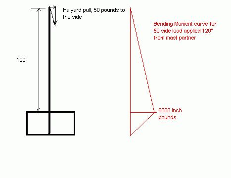
Let's say we have 50 pounds of sail side force at the mast tip being
dumped there by the halyard which gets it from the yard which is tied
to the sail, etc. Let's say we have 10' of mast from tip to mast
partner. Then we would have 10 x 50 = 500 ft pounds of bending at the
mast partner. Let's call that 500x12=6000 inch pounds.
Let's say we have a 3" round wooden mast to start with. Recall that the
maximum bending stress in a round section will be Mc/I where M is the
bending moment (in inch pounds), c is the distance from the center of
the section to the outer fiber (1.5" in this example), and I is the
"moment of inertia" of the round section. A peak at the handbook says
for a round section the I = .78 x r^4 or .78 x 1.5x1.5x1.5x1.5 = 3.9
inches to the fourth. With a predicted bending moment of 6000 inch
pounds it works out as a maximum stress of s=6000 x 1.5 / 3.9 =2300
psi. Good wood is stronger than that, maybe up to 10,000 psi if you are
rich enough for perfect Sitka spruce. But Lowes pine maybe, maybe not.
No knots or cracks near the mast partner please.
NOW, LET US ADD A METAL DOUBLER...
Ok, maybe the skipper is getting a little worried. He has a bunch of
fat people on board for the first time and has stability he has never
imagined before. The wind is picking up and he is in a position to
"blow the sticks off" as they used to say. When he gets home he slides
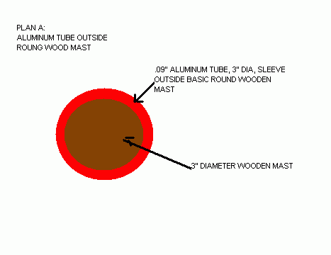
an aluminum tube over say the bottom 4' of the mast such that it
extends from the step to a foot or two above the mast partner. It is a
sliding fit, not glued or fastened so that the two pieces are locked
together. But the fit is good enough that the wood and tube must bend
together. They will share the load.
IT BECOMES A QUESTION OF STIFFNESS...
...and stiffness in bending is determined by our old friends E and I.
Recall that E is the "modulus of elasticity" of the material. Think of
it as a spring rate. To measure E you might take a 10" bar of the
material with say a 1" cross section, put it in a universal testing
machine (like the one Vincent Price used to commit suicide in "The
Fly"), pull on the ends of the bar while you measure the stretch of the
bar. Almost all structural materials are "elastic" in that they stretch
and rebound like a rubber band as long as you don't overdo it. So if
you put a 10" aluminum bar as described into the machine and stretched
it with 1000 pounds it would stretch a thousandth of an inch and it
would have an E of 1000x10/.001=10 million. And you would have the
right answer! All aluminums have an E of 10 million more or less as
long as you don't stretch them beyond their "elastic limit" (at which
point they don't rebound but instead stay stretched for ever).
So now you put a stick of wood in the machine and repeat the test. My
handbook you would expect it to stretch about about .007 thousandths.
Because the handbook says the E for wood is about 1.5 million. But wood
is really fuzzy stuff and it will vary a lot more than aluminum. But in
general wood is say 1/7th as stiff as aluminum in such a test.
Next, we will calculate the EI 's of the two pieces. We already know
the wood has an I of 3.9 and an E of 1.5 million, so EI is 5.8 million.
If you knew the real applied load you could calculate the actual bend
of the mast but if your mast is tapered then the I is changing
constantly and it ain't easy and is best left to the student.
We didn't say how thick the aluminum tube was but let's say it is .09"
thick and 3" in diameter. Another quick peek at the old handbook and we
find I for a tube is 3.14 x t x r^3 so for this tube is would be 3.14 x
.09 x 1.5x1.5x1.5= .95 inches to the fourth. So EI for the aluminum
tube here would be .95 x 10 million = 9.5 million.
The tube is about twice as stiff as the wood. If they bend to the same
curve, and they must if they fit together, then the tube will absorb
about twice as much bending as the wood. So if the bending was 6000 in
pounds, then I would expect the wood part to take about 2000 inch
pounds of that and the aluminum tube about 4000 inch pounds. So the
stress in the wood is greatly reduced.
LET US NOT CELEBRATE YET....
You have to check the stress in the tube next. Back to Mc/I. For the
tube we already know the numbers. Stress here is = 4000x1.5/.95 = 6300
psi. OK, celebrate. Almost any structural aluminum can handle that.
ONE MORE WORRY...
What happens where the tube ends leaving the wood to soldier on alone?
Same old problem except that the bending moment higher up the mast will
be less. For example if the tube extends 2' above the partner, then the
bending moment there now has an 8' arm instead of a 10', so the bending
there is 8 x 50 x 12 = 4800 inch pounds instead of 6000. But it is
still a worry and these transitions are always trouble makers. There
was a saying back at the missile factory that "structures always fail
at the joints." Yes.
NOW ON TO PLAN B....
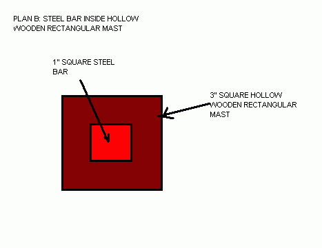
...Let's say the above mast was made with a square cross section, say
3" square with a 1" square hole down the middle. Can we reinforce it
with a 1" square steel bar placed in the hollow center.
Same procedure as above. First the I of the new mast. Another quick
peek at the handbook and we find the I of a square is (a^4)/12. So for
this square mast we start by taking I = 3x3x3x3/12 =6.8 inches fourth.
But the center 1" is hollow so we must subtract that where Icenter =
1x1x1x1/12 = .08 inches fourth. Total is 6.8-.08=6.7 inches fourth and
note that almost no I was lost due to the hollowing of the mast (and
not much weight was saved for that matter either). So EI for the wood
mast at the partner would be 6.7 x 1.5 million =10 million. Note that
the square wood section is much stiffer than the round of equal width.
Now for the EI of the steel bar placed in the hollow center. We already
know the I is a tiny .08 inches fourth. But E for steel is about 30
million, 20 times stiffer than wood. So the steel filler has EI of 2.4
million.
The steel EI is only about one fourth that of the basic wooden mast so
here I would expect the wood section to take say 4800 inch pounds of
the total of 6000 inch pounds which the steel's share is about 1200
inch pounds. Nothing like the benefit of the outer aluminum tube and
that is to be expected because in bending it is the outer fibers of the
thing that are doing all the work. Lastly a quick check of the bending
stress in the steel would be something like stress = 1200 x .5 / .08
=7500 psi and there is no problem. The wood will fail long before the
steel. But I suppose you could see this system as giving the wood a 20
percent reduction in stress, or the mast is 20 percent stronger.
A LAST THOUGHT...
...I haven't gotten into the idea of adding fiberglass or carbon cloth
reinforcement to the outer surface of the mast. For that to have any
meaning the exact layup of the fibers has to be known and even then I'm
not sure if I'm smart enough to figure it. Best left to the student. If
the fibers are stiff and mostly run the length of the mast then they
will be very effective in taking the bending. If they are very stiff
and thin, say a thin coating of carbon fibers running the length of the
mast, they might be so effective at taking the bending that they will
take essentially all of it right up until they snap, at which point you
are back again to just a wooden mast. Nothing simple about composite
stress analysis I think.
Contents
FROLIC2
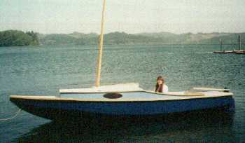
FROLIC2, CUDDY MULTI SKIFF, 20' X 5', 400 POUNDS EMPTY
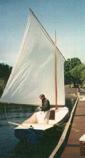
The photos show the prototype Frolic2 built by Larry Martin of Coos
Bay, Oregon. Larry built the boat quite quickly this past winter
including sewing the sail to the instructions given in the plans. He
reported sailing it for the first time on a ripping day with an
occasional 2' wave. I always advise testing a new boat in mild
weather, especially a new design, but Larry got away with it. Looking
at his photos, the neat work, and simple efficient rigging suggests
to me that Larry has been sailing small boats a long time.
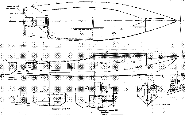
Frolic2 has a small cabin, probably only for one to sleep in because
the multichines that make the boat good in rough water also rob you
of floor space. To say it another way, the nice big floor space of a
flat bottomed sharpie is what pounds in rough water and makes you
uncomfortable. But Frolic2 has a 6' long cockpit so someone could
sleep there too. There is bench seating. The cabin top has a slot top
down the center and you can stroll right through the cabin standing
upright in good weather and out the front bulkhead to the beach. The
mast is offset to one side so you will need not have to step around
it. Phil Bolger showed us how to do this about 15 years ago and it
works. But Larry went conventional with his boat, mounting the mast
on centerline and decking in the front of the cabin. On a slot top
cabin you use a simple snap on tarp to cover the slot in rain or cold
or bugs.
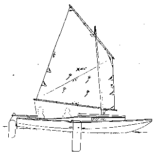
Frolic2 was designed for rough water, long and lean, especially in
the bow, and with multiple chines. She's really a takeoff of my Toto
canoe in shape. Larry omitted the motor well you see in the lines,
and the oarlocks too (The wind must blow just right all the time in
Oregon?) but I intended this to be a multi skiff sort of boat with
rowing and motoring abilities. You can't row a boat of this size in
any wind or waves but in a calm you can travel far if you have
patience. I didn't fool around with a gadget motor mount - I put the
motor well right in the middle and offset the rudder instead of the
other way around. This worked out very well on the high powered
Petesboat. We'll see how it goes on a narrow boat because the second
prototype is getting the blueprint well as you see in the photo below
of the Colorado Frolic2 still being built. You need little power on a
boat like this, 2 or 3 hp is more than enough.
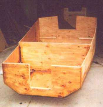
The lug rig is for quick easy stowing, rowing, and towing. (The
blueprint sail is actually the same size and shape as that of a Bolger
Windsprint, a boat which weighs maybe a third as much as Frolic2 and is
much narrower. But I think the Windsprint might be over sparred for its
size and weight.) Larry reports the rig is about right for the boat,
sailing fine with a reef in and three adults on a windy day. The lug
sail can be closer winded reefed than when full, perhaps because the
sail is then shorter and the yard better controlled (less sail twist).
For that matter a sharpie sprit sail the same size as the lug might be
smarter in rough water conditions if you can live with the long mast.
Switching rigs won't be hard. The mast can be relocated almost anywhere
in the slot top without altering the hull to any degree. You just need
extra partner and step fittings.
Update, 2006. Jeff Blunk's Colorado Frolic2 eventually found its way
to Illinois and then to our Rend Lake Messabout in the hands of
Richard Harris. We had a chance to try it out and I was quite
pleased. It was fast and powerful. At one point with three men on
board, with Max at the tiller, I went forward to tweak the sail which
took a couple of minutes with me staring up at the sail. That done I
looked back and saw that we were really rolling along.

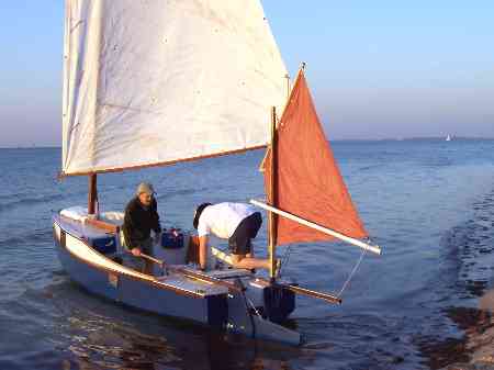
And Gary Blankenship's Frolic2 completed the Everglades 300 mile
challange with him reporting sailing for hours at 7 knots or more.
Last count he completed three of the challenges with a 4th overall in
2007. Here is Gary's Frolic2:
Construction is with taped seams from eleven sheets of 1/4" plywood
and two sheets of 1/2" plywood.
Plans for Frolic2 are $35.
Contents
Prototype News
Some of you may know that in addition to the one buck catalog
which now contains 20 "done" boats, I offer another catalog of 20
unbuilt prototypes. The buck catalog has on its last page a list
and brief description of the boats currently in the Catalog of
Prototypes. That catalog also contains some articles that I wrote
for Messing About In Boats and Boatbuilder magazines. The Catalog
of Prototypes costs $3. The both together amount to 50 pages for
$4, an offer you may have seen in Woodenboat ads. Payment must be
in US funds. The banks here won't accept anything else. (I've got
a little stash of foreign currency that I can admire but not
spend.) I'm way too small for credit cards.
I think David Hahn's Out West Picara is the winner of the Picara
race. Shown here on its first sail except there was no wind.
Hopefully more later. (Not sure if a polytarp sail is suitable
for a boat this heavy.
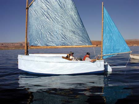
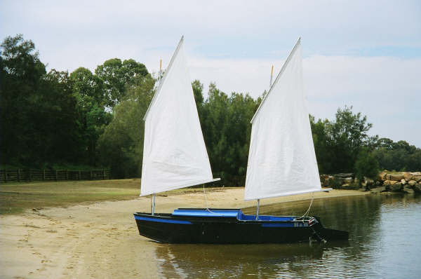
Here is a Musicbox2 I heard about through the grapevine.
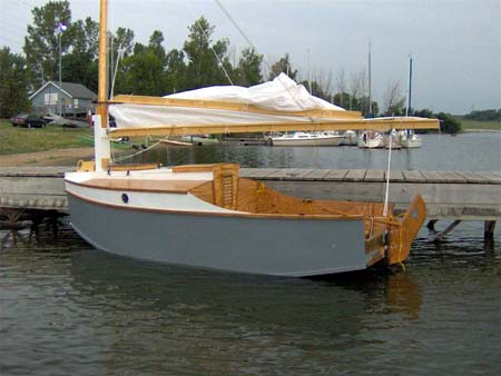
This is Ted Arkey's Jukebox2 down in Sydney. Shown with the
"ketchooner" rig, featuring his own polytarp sails, that is shown
on the plans. Should have a sailing report soon.
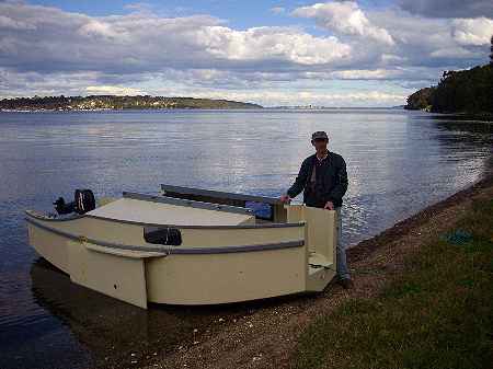
And the Vole in New York is Garth Battista's of
www.breakawaybooks.com, printer of my book and Max's old outboard
book and many other fine sports books. Beautiful job! Garth is
using a small lug rig for sail, not the sharpie sprit sail shown
on the plans, so I will continue to carry the design as a
prototype boat. But he has used it extensively on his Bahamas
trip towed behind his Cormorant. Sort of like having a compact
car towed behind an RV.

And a new Down Under Blobster is off cruising under outboard
power as it waits for its sailrig.
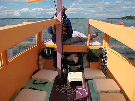
A view of the Caroline prototype showing a lot of the inside,
crew on fore deck. Beautiful color:
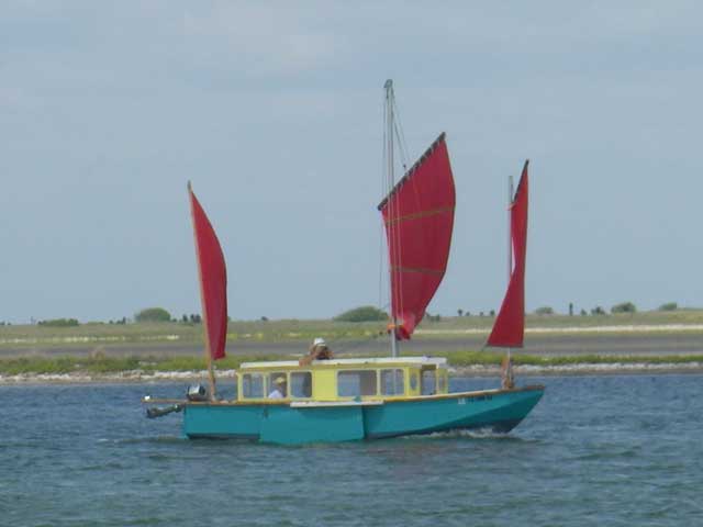
And here is another making I think its maider voyage in the Texas
200. (I'm told the Chinese rig will be replaced by the blueprint
rig.)
I gotta tell you that on the Caroline bilge panels I made an
error in layout and they are about 1" too narrow in places on the
prototype plans. I have them corrected but it always pays, even
with a proven design, to cut those oversized and check for fit
before final cutting.
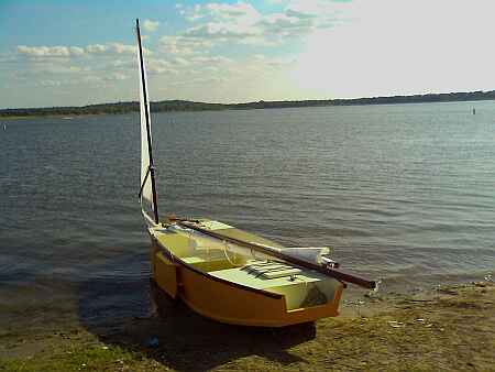
And a Deansbox seen in Texas:
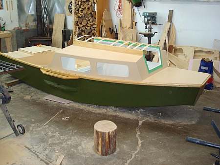
A Twister goes together in good shape. He moved the cabin
bulkhead aft for more cabin, less cockpit:
Contents
AN INDEX OF PAST ISSUES
BACK ISSUES LISTED
BY DATE
SOME LINKS
Mother of All Boat
Links
Cheap
Pages
Duckworks
Magazine
The Boatbuilding
Community
Kilburn's Power
Skiff
Bruce Builds
Roar
Dave
Carnell
Rich builds
AF2
JB Builds
AF4
JB Builds
Sportdory
Hullforms Download (archived copy)
Plyboats Demo Download (archived
copy)
Brokeboats (archived copy)
Brian builds Roar2 (archived copy)
Herb builds AF3 (archived copy)
Herb builds RB42 (archived copy)
Barry Builds
Toto
Table of
Contents
