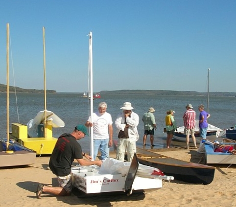
A perfect sunny day and boats gather at Sail Oklahoma 2011.
Contents:
Contact info:
Jim Michalak
118 E Randall,
Lebanon, IL 62254Send $1 for info on 20 boats.
Jim Michalak's Boat Designs
118 E Randall, Lebanon, IL 62254
A page of boat designs and essays.
(15 October) This issue will repeat the Sail Area Math essay. The November issues will present Sail Oklahoma 2011!
THE BOOK IS OUT!
BOATBUILDING FOR BEGINNERS (AND BEYOND)
is out now, written by me and edited by Garth Battista of Breakaway Books. You might find it at your bookstore. If not check it out at the....ON LINE CATALOG OF MY PLANS...
...which can now be found at Duckworks Magazine. You order with a shopping cart set up and pay with credit cards or by Paypal. Then Duckworks sends me an email about the order and then I send the plans right from me to you.

|
Left:
A perfect sunny day and boats gather at Sail Oklahoma 2011. |
|
|
Sail Area Math
BACKGROUND...I have to rerun this essay every year. This subject is the most common area where tinkerers of designs get in trouble. It always has been and always will be. Anytime you modify the sail rig you need to keep this math in mind.
If you look at the picture below of the sail rig of Mayfly12 you will see on the sail some (fuzzy) writing (that didn't scan well) that says "55 square feet" to the left of a small circle that represents the center of that area (honest).
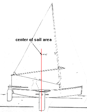
The center of that area is often called a "centroid" and you will see it is placed more or less directly above the center of the leeboard's area. That is very important.
As you might imagine a shallow flat hull like this with a deep narrow leeboard wants to pivot around that leeboard. If the forces of the sail, which in a very general way can be centered at the sail's centroid, push sideways forward of the leeboard, the boat will tend to fall off away from the wind. You should be able to hold the boat on course with the rudder but in that case the rudder will have "lee helm" where you have to use the rudder to push the stern of the boat downwind. The load on the rudder will add to the load of the leeboard. Sort of a "two wrongs make a right" situation and generally very bad for performance and safety in that if you release the tiller as you fall overboard the boat will bear off down wind without you.
If the centroid is aft of the leeboard you will have "weather helm", a much better situation. The rudder must be deflected to push the stern towards the wind and the force on it is subtracted from the load on the leeboard. Not only that, but when you release the tiller as you fall overboard the boat should head up into the wind and stall and wait for you if you are lucky. It's a good deal but if you overdo it you can end up with too much load on the rudder.
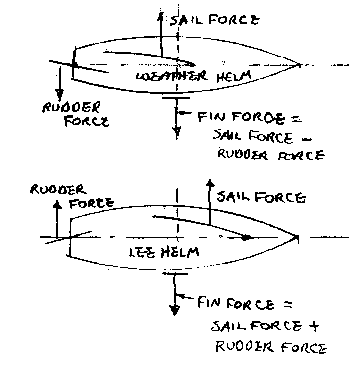
This balance problem is actually one of the few things about sail rigs that is not arbitrary. The type of rig and its area are pretty arbitrary depending on how fast you want to go, how much you weigh, etc. But balance is quite important and is one of the areas where backyard boaters get into trouble, sometimes changing the boat or rig with no thought of balance. So before you go doing that you should do a little homework. This essay will tell you how to figure sail area and find the centroid.
One last item: the balance situation shown for Mayfly12 is what I have found to be best for this type of boats. Boats with large fin keels don't balance that way - usually the sail centroid is well forward of the keel centroid. That distance is called the "lead". That type of boat is not within my personal experience and I'm not going to get into that. But you still would have to figure the area and centroid.
THREE SIDED SAILS...
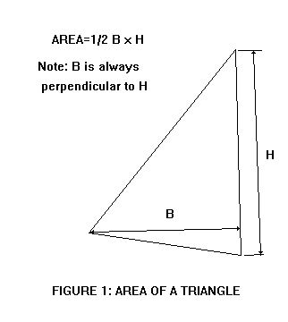
This one is really easy. The area is just the base time the height divided by 2. Any side can be the base and the height is aways at a right angle to the base.
So when you lay out the sail you draw it up on thin paper to the same scale as your hull drawing with the leeboard (or daggerboard or centerboard) lowered. Draw a line through the center of the board straight up. Now we're going to locate the scale sail on the boat such that it's centroid falls very close to that line.
Here's how you find the centroid of a triangular sail.
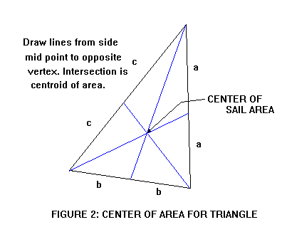
Find the midpoint of each side and and draw a line from that midpoint to the vertex opposite it. The three lines will intersect at the centroid. Actually you only need to find the intersection of two lines but the third line is a good check.
That's it! Now you can take you scale sail drawing and slide it around your hull drawing until the centroid is on that line drawn up from the hull's board. Move it up and down and tilt it until you like the way it looks. But don't cheat much forward or aft of that line.
FOUR SIDED SAILS...
To find the area of a four sided sail you just divide it into two triangles, find the area of each triangle as above, and add the two together.
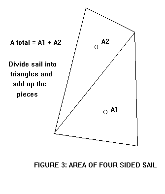
Now to find the centroid of the four sider. Start by finding the centroids of the two triangles that make up the four sided sail as shown above. Now draw a line from one triangle centroid to the other. The centroid of the four sider is on that line somewhere.
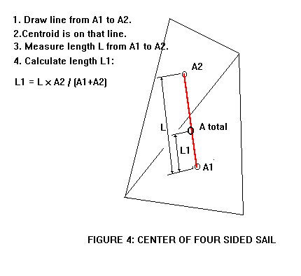
To find exactly where the centroid is on that line, measure the length of that connecting line. You need not use the same scale as is used on the drawing. I prefer to use a millimeter scale for this measurement. Then get out the calculator and work the formula shown in the Figure 4. Let's say for example the length of the connecting line on the scale drawing measures 120 mm (that is measurement L). Let's say the example sail has a lower triangle area of 50 square feet (that is A1). The upper triangle is 35 square feet (that is A2). So the total sail area is 50 + 35 = 85 square feet. The length L1, which will exactly locate the sail's total centroid, is L1 = 120 x 35/85 = 49.4 mm. So you take that millimeter scale and measure up from A1 centroid on the connecting line 49.4 mm and make a tick mark on the connecting line. That is the centroid of the total sail.
Another way to find the centroid, especially of a really odd shaped sail, is to take the scale drawing of the sail and cut it out. Then balance the cutout on a knife edge and mark the balance line, rotate the cutout on the knife edge about 90 degrees and rebalance and mark the new balance line. The centroid lies at the intersection of the two line.
Another way is to dangle the cutout on a pin stuck through a corner and into a wall marked with a vertical line that passes through the pin point. Mark the line that passes through that pivot corner and a vertical. Then rotate the cutout to hang it from another corner, and mark a second line through the second pivot corner and a vertical. The centroid lies at the intersection of those two lines. Back at the missle factory the designers had a favorite place, complete with pivot pin socket hole and vertical line, to hang these cutouts and that place was known as the "weighing wall". Meanwhile the super computer cranked away next door but its answers weren't to be trusted unless they agreed with the cutout hanging at the weighing wall.
RIGS WITH MANY SAILS...
Figure 5 shows the rig for Viola22. It has a main gaff sail of 177 square feet, and a mizzen sail of 45square feet. Where is the centroid of the assembly?
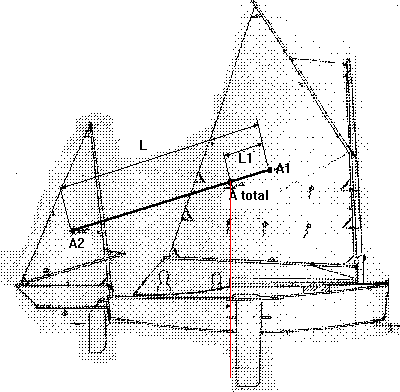
It's done exactly as with Figure 4. Draw a line connecting the areas of the two sails. Measure the length of the connecting line. Then run through the same equation as in Figure 4. Nothing to it.
One thing I might point out about the Viola22 rig is that the total centroid falls near the aft edge of the leeboard. By my experience the mizzen is not as efficient as its area suggests so it needs to be a bit oversized by normal rules, fudging the total centroid aft. I think in general the aft sails operate in the scrambled flow of the forward sail, causing loss of force back there.
Jonsboat
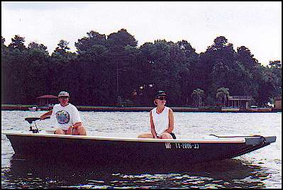
JONSBOAT, POWER SKIFF, 16' X 5', 200 POUNDS EMPTY
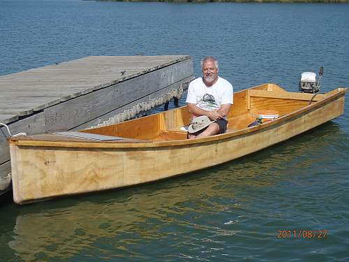
Jonsboat is just a jonboat. But where I live that says a lot because most of the boats around here are jonboats and for a good reason. These things will float on dew if the motor is up. This one shows 640 pounds displacement with only 3" of draft. That should float the hull and a small motor and two men. The shape of the hull encourages fast speeds in smooth water and I'd say this one will plane with 10 hp at that weight, although "planing" is often in the eye of the beholder. I'd use a 9.9 hp motor on one of these myself to allow use on the many beautiful small lakes we have here that are wisely limited to 10 hp. The prototype was built by Greg Rinaca of Coldspring, Texas and his boat is shown above when first launched with a trolling motor. But here is another one finished about the same time by Chuck Leinweber of Harper, Texas:
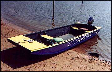
In the photo of Chuck's boat you can see the wide open center that I prefer in my own personal boats. To keep the wide open boat structurally stiff I boxed in the bow, used a wide wale, and braced the aft corners.
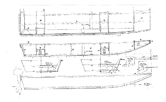
I usually study the shapes of commercial welded aluminum jonboats. It's surprising to see the little touches the builders have worked into such a simple idea. I guess they make these things by the thousands and it is worth while to study the details. Anyway, Jonsboat is a plywood copy of a livery boat I saw turned upside down for the winter. What struck me about that hull was that its bottom was constant width from stem to stern even though the sides had flare and curvature. When I got home I figured out they did it and copied it. I don't know if it gives a superior shape in any way but the bottom of this boat is planked with two constant width sheets of plywood.
Greg Rinaca put a new 18 hp Nissan two cycle engine on his boat, Here is a photo of it:
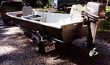
The installation presented a few interesting thoughts. First I've been telling everyone to stick with 10 hp although it's well known that I'm a big chicken about these things. Greg reported no problems and a top speed of 26 mph. I think the Coast Guard would limit a hull like this to about 25 hp, the main factors being the length, width, flat bottom, and steering location. Second, if you look closely at the transom of Greg's boat you will see that he has built up the transom in the motor mount area about 2". When I designed Jonsboat I really didn't know much about motors except that there were short and long shaft motors. I thought the short ones needed 15" of transom depth and didn't really know about the long shafts. Jonsboat has a natural depth of about 17" so I left the transom on the drawing at 17" and did some hand waving in the drawing notes about scooping out or building up the transom to match the requirements of your motor.
I think the upshot of it all is that short shaft motors need 15" from the top of the mount to the bottom of the hull and long shaft motors need 20". There was a lot of discussion about where the "cavitation" plate, which is the small flat plate right above the propellor, should fall with respect to the hull. I asked some expert mechanics at a local boat dealer and they all swore on a stack of tech manuals that a high powered boat will not steer safely if the cavitation plate is below the bottom of the hull, the correct location being about 1/2" to 1" above the bottom. But Greg had the Nissan manual and it said the correct position is about 1" BELOW the bottom. Kilburn Adams has a new Yamaha and its manual says the same thing. So I guess small motors are different from big ones in that respect.
But it seems to be not all that critical, at least for the small motors. Greg ran his Jonsboat with the 18 hp Nissan with the original 17" transom for a while and measured the top speed as 26 mph. Then he raised the transom over 2" and got the same top speed!
There is nothing to building Jonsboat. There five sheets of plywood and I'm suggesting 1/2" for the bottom and 1/4" for everything else. It's all stuck together with glue and nails using no lofting or jigs. I always suggest glassing the chines for abrasion resistance but I've never glassed more than that on my own boats and haven't regretted it. The cost, mess, and added labor of glassing the hull that is out of the water is enormous. My pocketbook and patience won't stand it. Glassing the chines and bottom is a bit different because it won't show and fussy finishing is not required.
Plans for Jonsboat are $25.
Prototype News
Some of you may know that in addition to the one buck catalog which now contains 20 "done" boats, I offer another catalog of 20 unbuilt prototypes. The buck catalog has on its last page a list and brief description of the boats currently in the Catalog of Prototypes. That catalog also contains some articles that I wrote for Messing About In Boats and Boatbuilder magazines. The Catalog of Prototypes costs $3. The both together amount to 50 pages for $4, an offer you may have seen in Woodenboat ads. Payment must be in US funds. The banks here won't accept anything else. (I've got a little stash of foreign currency that I can admire but not spend.) I'm way too small for credit cards.
I think David Hahn's Out West Picara is the winner of the Picara race. Shown here on its first sail except there was no wind. Hopefully more later. (Not sure if a polytarp sail is suitable for a boat this heavy.
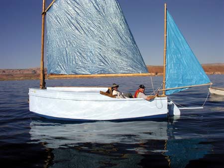
Here is a Musicbox2 out West.
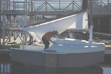
This is Ted Arkey's Jukebox2 down in Sydney. Shown with the "ketchooner" rig, featuring his own polytarp sails, that is shown on the plans. Should have a sailing report soon.
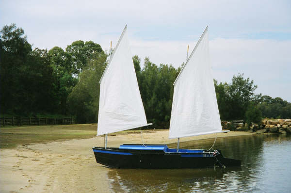
And the Vole in New York is Garth Battista's of www.breakawaybooks.com, printer of my book and Max's old outboard book and many other fine sports books. Beautiful job! Garth is using a small lug rig for sail, not the sharpie sprit sail shown on the plans, so I will continue to carry the design as a prototype boat. But he has used it extensively on his Bahamas trip towed behind his Cormorant. Sort of like having a compact car towed behind an RV.
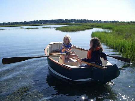
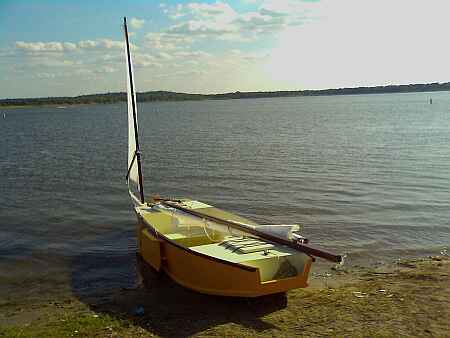
And a Deansbox seen in Texas:
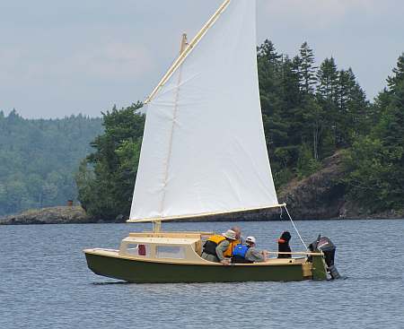
The prototype Twister gets a test sail with three grown men, a big dog and and big motor with its lower unit down. Hmmmmm.....
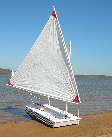
Jackie and Mike Monies of Sail Oklahoma have completed this Catbox. I sailed it at the meet and it is a keeper. Full report very soon.
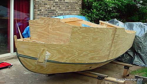
And the first D'arcy Bryn is ready for taping. You can follow the builder's progress at http://moffitt1.wordpress.com/ ....
And the first Brucesboat is in the water for testing. A full report soon.
OK, so he found a major league goof in my plans on fitting the bilge panels. He did some cut and fit and did a great job of salvaging the work, but I have corrected the drawing for the aft end of the bilge panel (I drew it in upside down!!)
AN INDEX OF PAST ISSUES
Hullforms Download (archived copy)
Plyboats Demo Download (archived copy)
Brokeboats (archived copy)
Brian builds Roar2 (archived copy)
Herb builds AF3 (archived copy)
Herb builds RB42 (archived copy)