Contents
Underwater Board Shape 2
ASPECT RATIO AGAIN! ....
...is all about shape. In particular we will take a look at the overall
shape of a sail or underwater board. Aspect ratio, let's call it AR,
has always been a concern to aircraft designers all the way back to the
Wright brothers who did a lot more than just fly the first airplane.
They were also pretty good scientists, I think, and in the Air Force
Museum I recall seeing a wind tunnel built by the Wrights, very state
of the art back then.
Anyway, AR is defined as AR=bxb/S where "b" is the span of wing in
aircraft terms and "S" is the total area of the wing. Look at this:
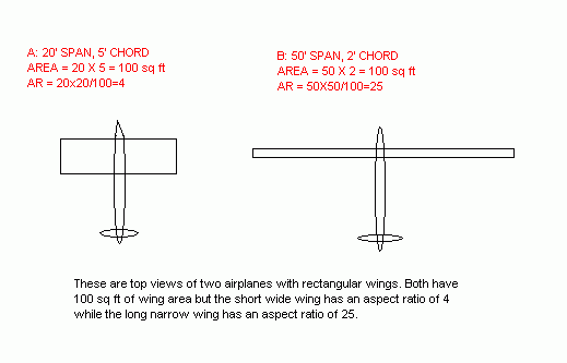
What this is supposed to show is two airplanes from a top view. They
have the same wing area and if they had the same weight and wing cross
section they should have the same stall speed and so forth. But they
would fly totally different from each other. The plane with the long
narrow wing might be a modern sail plane. High powered jets might have
a short wide wing. So what's the deal with the shape?
I GOTTA TELL YOU...
...that aerodynamics seems at times to be like witchcraft, with
correction factors piled on high to theories that never seem to explain
everything. Luckily a hundred years of research has left us with many
choices of correction factors. Hey! One day I'm sitting at the missile
factory and the boss is agonizing over having to add little studs to
his missile so it will fit a new launcher. "They will ruin the range
with extra parasitic drag, everybody knows that," says the aero
department. "But we gotta have them," says the boss. "We'll build it
with studs and fly it and see what happens," he says. The test goes
very well indeed, the studded missile outflying the nonstudded. "The
studs acted like vortex generators and energized the boundary layer
thus reducing drag, everybody knows that," says the same aero
department. Well, they have lots of majic wands in aero but they know
their aspect ratio effects. To start take a look at this:
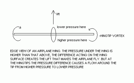
This is an airplane viewed head on. The thing flies because the air
pressure acting on the underside of the wing is higher than that on the
top. But in real life the air near the tip will try to escape from the
bottom to the top by flowing around the tip, being pushed by the
difference in pressure there. It swirls from bottom to top as the plane
flies forward making a vortex. You can see them under certain
conditions as they cause swirling clouds to appear at the wingtip.
Now, this doesn't happen in wind tunnel testing of wing sections
because the wing model usually goes across the tunnel so that air can't
swirl around the end. That testing is supposed to be independent of
"3D" effects so the wing section test data is reallty for a
hypothetical wing of infinite span, no tip losses. So adjustments are
made to calculate the effect of real life wingspan. The effect is I
think mainly in increased drag and I don't recall ever seeing any
wingspan related adjustment to maximum lift.
Great efforts have been made to reduce the swirls such as twisted wing
tips, endplated wingtips and lately elaborate winglets on the tips.
But clearly a long narrow wing has less wingtip than a short wide wing.
NOW TO THE BOAT...
When a sailboat is close hauled, that is sailing close to the wind,
both the sail and the boat's underwater board are acting as airfoils,
the sail through the air and the board through the water. Here is an
end view....

The wind pressure on the sail causes a vortex at the top and bottom of
the sail, just like an airplane's wing held vertically. I've never
checked for them in real life but I suppose you could with tufts or
ribbons that will align to the air flow there. Or maybe a good excuse
to start smoking cigarettes could be made in saying you hope to view
the vortex at the bottom of the sail. Or if you are say an Englishman
you might sail in fog a lot and actually see the vortex.
The sideforce on the underwater board is a reaction to the sideforce
made by the sail in a close hauled sailboat. The board also acts like
an airfoil and actually flies through the water (which is about 1000
times as dense as air). One difference here is that the board has no
gap to the hull at the top. There can be no vortex there. Same with a
rudder or leeboard which extends past the water's surface. So it has
half of the usual vortex effect.
Hey! If you have a leeboard boat you can sometimes see the vortex at
the end of the board! I've done it with Piccup Pram. Raise the board a
bit to get the tip closer to the surface and effectively reducing the
aspect ratio. Get the boat close hauled in such a way that you can peer
over the side at the tip of the board. There it is! Looks like a white
rope twisting off the end of the board.
Now, you ask, what if the sail also extended to the deck? Would that
not eliminate one vortex. Yes and some sails have been made to do that.
I think large headsails of racing boats in particular can be made this
way. But they are deck sweepers and clearly are a big bother on the
usual day sailer. I remember reading somewhere that the gap needed to
prevent the vortex is quite small, say one tenth of the sail's width or
less. The sail on my Bolger Birdwatcher might approach this. You can
sort of get away with this on a Birdwatcher because you are always
supposed to be in the cabin. But even here the decksweeper is a very
dangerous thing. So a decksweeper sail is a feature I try to avoid.
DOWNWASH....
So far I'd be tempted to say "So What!" The short wide wing has bigger
tip vortices than the long narrow wing. But the aero guys point out
that the swirl produces a "downwash" over the entire wing, not a good
thing at all since the wing is supposed to be pushing us up. The aero
guys simply add the downwash to the real wind like this:
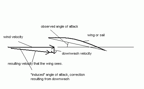
So what we have here is that the pilot sees he is flying at say 10
degrees to his flight path. But the wing tip vortices are swirling the
wind on the wings downward by say 5 degrees. So he is really flying at
5 degrees to the wind the wing is experiencing. That might not be a
huge factor to a pilot who can correct by changing the aircraft's pitch
and get the lift proper simply by finding the pitch that gives level
flight. He might find that the real limitation here is that on final
approach to the runway he is pitched so far upward that he can't see
the runway! I suppose the Concorde airliners were the best example
here. Short wide wings are great for supersonic flight, like say the
Space Shuttle, but they produce a downflow such that the required angle
of attack on landing resulted in the design of a folding nose to give
pilot vision over the bow.
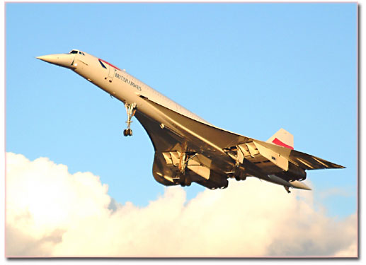
Now, according to the airfoil section data his wing might stall at say
15 degrees angle of attack. The plane might appear to have a flight
path of 30 degrees in very slow flight but the airflow local to the
wings is actually below the stall angle once you correct it for
downwash. I am guessing at all these numbers but I hope you see how it
works.
Let's contrast this with the sailplane with the wing aspect ratio of
25. His wing tips are tiny and so are his wing tip vortices and so is
the resulting downflow on his wings. He is approaching 2 dimensional
flow like the section tests in the wind tunnel.
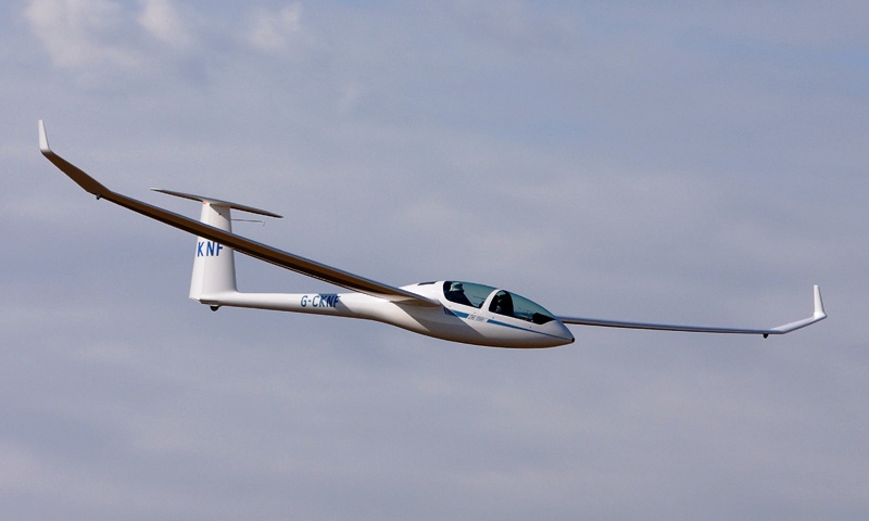
Of course the glider pilot's idea of "level flight" is different from
the Concorde's pilot. He is slowly gliding downward but the angle can
be quite low, maybe 50 to 1 in a super glider (I'm guessing). I am
going to guess again and say maybe his "cruising" speed is twice his
landing speed, unlike the Concord which might cruise at ten times its
landing speed. So the glider may not see downwash as a huge part of its
life. He flies and lands flat. The downwash issue has been designed out
when the long long high aspect ratio wing was designed in.
WHAT! MORE NUMBERS......
When the pilot tilts his plane upwards to correct for downwash a nasty
thing happens. See below...
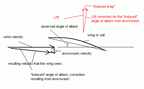
Same drawing as before but note that by adding pitch to account for the
downwash the wing's force also tilts backward and creates an added drag
component "induced" by the downwash. It is proportional to the
aircraft's lift and to the downwash.
The aero expression for calculating the induced drag coefficient (to be
added to the basic parasitic drag coefficient to calculate total drag)
is fairly straight forward. Essentially it is just (Cl x Cl)/(3.14 x
AR) where Cl is the lift coefficient and AR is the aspect ratio. And
right off the bat you can see that in our very first example the short
winged plane with AR=4 always has about six times as much induced drag
as the long winged plane with AR=25.
Induced drag is at its worst when the lift coefficient is high such as
when landing or high G maneuvers. It can become very high for short
wing airplanes. It can overwhelm other types of drag at times. A low
speed glide angle might be quite steep in the downward direction. Or if
thrown into a high G turn the short winged pylon racing airplane will
slow down a lot and lose his lead to the racer with the long narrow
wing. But the Concord cruising at mach 3 is at a very low value of Cl
and induced drag is of no concern then.
I suspect the close hauled sailor is always operating at a high value
of Cl or at least at the best lift/drag ratio his sail can produce. And
for the close hauled sailor that extra induced angle of attack comes
right out of his sail's ability to point into the wind. We'll take a
closer look at that next time.
Contents
FROLIC2
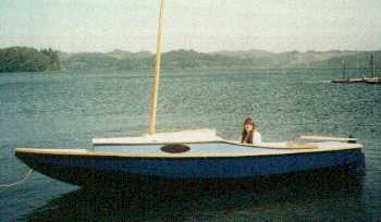
FROLIC2, CUDDY MULTI SKIFF, 20' X 5', 400 POUNDS EMPTY
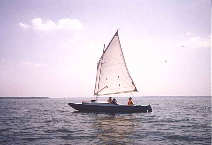
The photos show the prototype Frolic2 built by Larry Martin of Coos
Bay, Oregon. Larry built the boat quite quickly this past winter
including sewing the sail to the instructions given in the plans. He
reported sailing it for the first time on a ripping day with an
occasional 2' wave. I always advise testing a new boat in mild
weather, especially a new design, but Larry got away with it. Looking
at his photos, the neat work, and simple efficient rigging suggests
to me that Larry has been sailing small boats a long time.
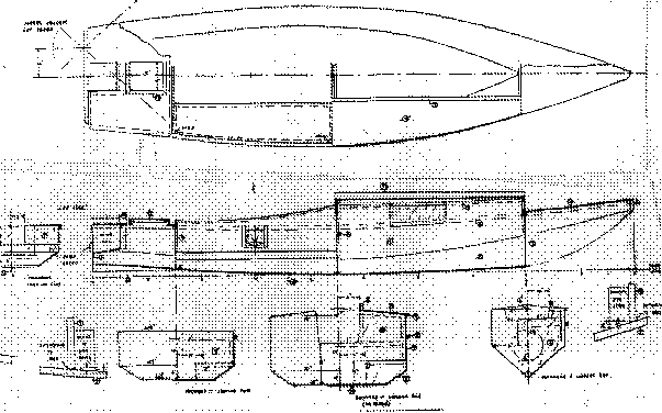
Frolic2 has a small cabin, probably only for one to sleep in because
the multichines that make the boat good in rough water also rob you
of floor space. To say it another way, the nice big floor space of a
flat bottomed sharpie is what pounds in rough water and makes you
uncomfortable. But Frolic2 has a 6' long cockpit so someone could
sleep there too. There is bench seating. The cabin top has a slot top
down the center and you can stroll right through the cabin standing
upright in good weather and out the front bulkhead to the beach. The
mast is offset to one side so you will need not have to step around
it. Phil Bolger showed us how to do this about 15 years ago and it
works. But Larry went conventional with his boat, mounting the mast
on centerline and decking in the front of the cabin. On a slot top
cabin you use a simple snap on tarp to cover the slot in rain or cold
or bugs.
Frolic2 was designed for rough water, long and lean, especially in
the bow, and with multiple chines. She's really a takeoff of my Toto
canoe in shape. Larry omitted the motor well you see in the lines,
and the oarlocks too (The wind must blow just right all the time in
Oregon?) but I intended this to be a multi skiff sort of boat with
rowing and motoring abilities. You can't row a boat of this size in
any wind or waves but in a calm you can travel far if you have
patience. I didn't fool around with a gadget motor mount - I put the
motor well right in the middle and offset the rudder instead of the
other way around. This worked out very well on the high powered
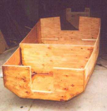
Petesboat. We'll see how it goes on a narrow boat because the second
prototype is getting the blueprint well as you see in the photo below
of the Colorado Frolic2 still being built. You need little power on a
boat like this, 2 or 3 hp is more than enough.
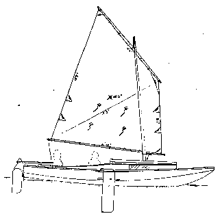
The lug rig is for quick easy stowing, rowing, and towing. (The
blueprint sail is actually the same size and shape as that of a Bolger
Windsprint, a boat which weighs maybe a third as much as Frolic2 and is
much narrower. But I think the Windsprint might be over sparred for its
size and weight.) Larry reports the rig is about right for the boat,
sailing fine with a reef in and three adults on a windy day. The lug
sail can be closer winded reefed than when full, perhaps because the
sail is then shorter and the yard better controlled (less sail twist).
For that matter a sharpie sprit sail the same size as the lug might be
smarter in rough water conditions if you can live with the long mast.
Switching rigs won't be hard. The mast can be relocated almost anywhere
in the slot top without altering the hull to any degree. You just need
extra partner and step fittings.
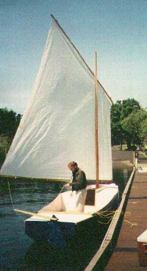
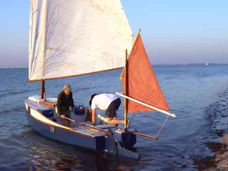
Update, 2006. Jeff Blunk's Colorado Frolic2 eventually found its way
to Illinois and then to our Rend Lake Messabout in the hands of
Richard Harris. We had a chance to try it out and I was quite
pleased. It was fast and powerful. At one point with three men on
board, with Max at the tiller, I went forward to tweak the sail which
took a couple of minutes with me staring up at the sail. That done I
looked back and saw that we were really rolling along.
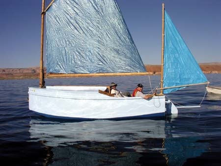
And Gary Blankenship's Frolic2 completed the Everglades 300 mile
challenge with him reporting sailing for hours at 7 knots or more.
Last count he completed five of the challenges with a 4th overall in
2007 and 7th in 2012. Here is Gary's Frolic2:
Construction is with taped seams from eleven sheets of 1/4" plywood
and two sheets of 1/2" plywood.
Plans for Frolic2 are $35.
Contents
Prototype News
Some of you may know that in addition to the one buck catalog
which now contains 20 "done" boats, I offer another catalog of 20
unbuilt prototypes. The buck catalog has on its last page a list
and brief description of the boats currently in the Catalog of
Prototypes. That catalog also contains some articles that I wrote
for Messing About In Boats and Boatbuilder magazines. The Catalog
of Prototypes costs $3. The both together amount to 50 pages for
$4, an offer you may have seen in Woodenboat ads. Payment must be
in US funds. The banks here won't accept anything else. (I've got
a little stash of foreign currency that I can admire but not
spend.) I'm way too small for credit cards.
I think David Hahn's Out West Picara is the winner of the Picara
race. Shown here on its first sail except there was no wind.
Hopefully more later. (Not sure if a polytarp sail is suitable
for a boat this heavy.
Here is a Musicbox2 out West.

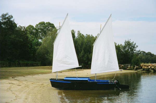
This is Ted Arkey's Jukebox2 down in Sydney. Shown with the
"ketchooner" rig, featuring his own polytarp sails, that is shown
on the plans. Should have a sailing report soon.
And the Vole in New York is Garth Battista's of
www.breakawaybooks.com, printer of my book and Max's old outboard
book and many other fine sports books. Beautiful job! Garth is
using a small lug rig for sail, not the sharpie sprit sail shown
on the plans, so I will continue to carry the design as a
prototype boat. But he has used it extensively on his Bahamas
trip towed behind his Cormorant. Sort of like having a compact
car towed behind an RV.
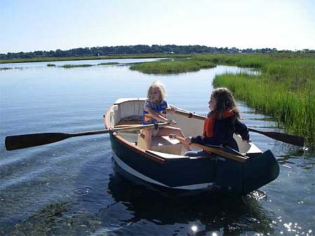
And a Deansbox seen in Texas:
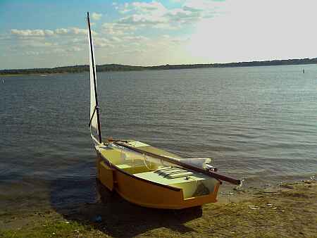
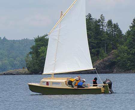
The prototype Twister gets a test sail with three grown men, a
big dog and and big motor with its lower unit down. Hmmmmm.....
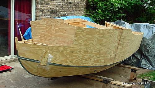
And the first D'arcy Bryn is ready for taping. You can follow the
builder's progress at http://moffitt1.wordpress.com/ ....
And the first Brucesboat is in the water for testing. A full
report soon.

OK, so he found a major league goof in my plans on fitting the
bilge panels. He did some cut and fit and did a great job of
salvaging the work, but I have corrected the drawing for the aft
end of the bilge panel (I drew it in upside down!!)
And a Hapscut goes together in Texas. He has scarfed some
material on the stern to finish the boat with a built in motor
well like Laguna. Good idea:
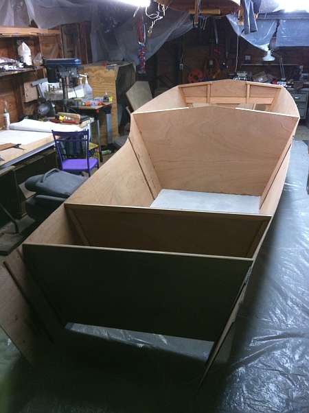
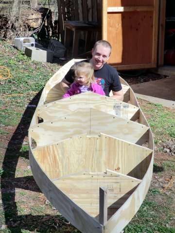
And here is a custom project going together so quickly that I am
going to hold releasing prototype plans, just release "done"
plans in a few weeks. He also already has a crew...
Contents
AN INDEX OF PAST ISSUES
BACK ISSUES LISTED
BY DATE
SOME LINKS
Mother of All Boat
Links
Cheap
Pages
Duckworks
Magazine
The Boatbuilding
Community
Kilburn's Power
Skiff
Bruce Builds
Roar
Dave
Carnell
Rich builds
AF2
JB Builds
AF4
JB Builds
Sportdory
Hullforms Download (archived copy)
Puddle Duck
Website
Brian builds Roar2 (archived copy)
Herb builds AF3 (archived copy)
Herb builds RB42 (archived copy)
Barry Builds
Toto
Table of
Contents
