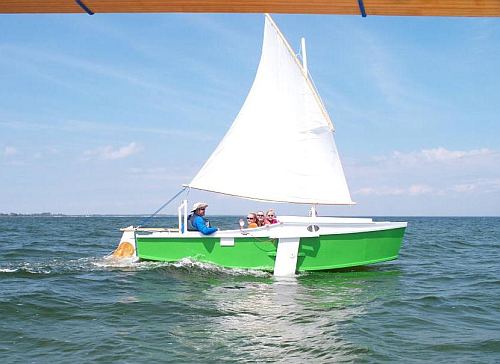
Scott Gosnelle takes his family out in his new Normsboat.
Contents:
Contact info:
Jim Michalak
118 E Randall,
Lebanon, IL 62254Send $1 for info on 20 boats.
Jim Michalak's Boat Designs
118 E Randall, Lebanon, IL 62254
A page of boat designs and essays.
(15April2013) This issue will continue the old "drawing a boat" essays that first ran in 2005, in particular finding the "true shapes" of twisted plywood panels with the PC. The 1 May issue will present some thoughts about leeboards and such.
THE BOOK IS OUT!
BOATBUILDING FOR BEGINNERS (AND BEYOND)
is out now, written by me and edited by Garth Battista of Breakaway Books. You might find it at your bookstore. If not check it out at the....ON LINE CATALOG OF MY PLANS...
...which can now be found at Duckworks Magazine. You order with a shopping cart set up and pay with credit cards or by Paypal. Then Duckworks sends me an email about the order and then I send the plans right from me to you.
MESSABOUT NOTICE:
THE REND LAKE MESSABOUT WILL TAKE PLACE ON JUNE 7 and 8 AT THE PINTAIL LOOP OF THE NORTH SANDUSKY CAMP GROUND AT REND LAKE IN SOUTHERN ILLINOIS. USUALLY THE SANDUSKY CAMP GROUNDS MIGHT BE FULL FOR THAT WEEKEND. BUT SOME OF OUR BOATERS HAVE RESERVED SOME OF THE SITES THERE SO YOU (AND I) MIGHT PASS THAT WAY FIRST SINCE SEVERAL TENTERS CAN SHARE A CAMPSITE. IF NOT, THEN I WOULD TRY THE WAYNE FITZGERRELL STATE CAMPGROUND WHICH IS ON THE MAIN CAUSEWAY LEADING TO SANDUSKY. THEIR WEBSITE SAYS IT IS STRICTLY FIRST COME FIRST SERVE, NO RESERVATIONS ALLOWED. IT IS A VERY QUICK DRIVE FROM THERE TO SANDUSKY. HOPE TO SEE YOU THERE!

|
Left:
Scott Gosnelle takes his family out in his new Normsboat. |
|
|
DRAWING BOATS 6
TO RECAP...
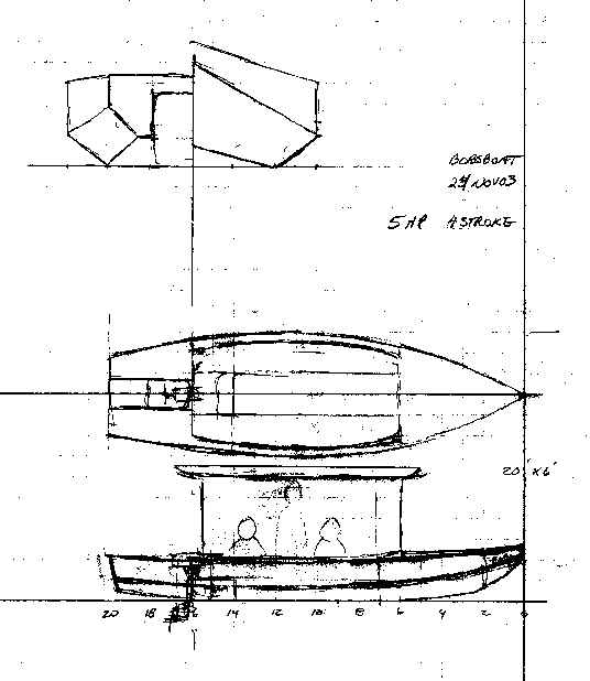
Last time we had Bobsboat designed to the point where we figured out the shapes of the simpler panels such as the bulkheads, transom, sides and bottom. When we got to the bilge panels we were stumped because they are twisted and the techniques used with the old fashioned drawing board require us to get an "edge" view of a curved panel before we can draw its expanded shape. And there is no way to draw the edge view of a twisted panel. What to do?
Now imagine that twisted bilge panel is divided into triangles like this:
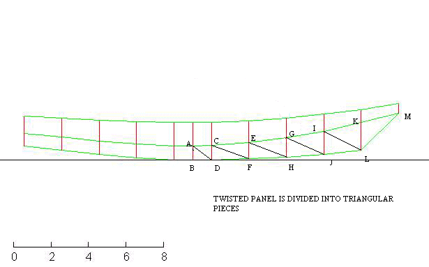
You can imagine that you could form a panel this way to fill the gap between the bottom and side - the desired bilge panel. The first time I read of this was about ten years ago when Dave Carnell, who never throws anything away, presented a Sam Rabl essay on the subject in Boatbuilder magazine. I think Sam wrote the article in the 1950's and maybe it was a summary of how the work was done in shipyards in WW2. In Sam's day the work was all done on the old fashioned drawing board.
Here is how it works. You have your three view line drawing available and you divide the desired panel into triangles as shown above. You label each intersection and using your table of offsets or by measuring the lines drawing you record in xyz coordinates the location of each intersection. Now, if you know the xyz location of each intesection you can figure the true lengths of all the lines between intersections. Once you know the true length of each line you can draw each triangle in its true flat pattern shape. In this case shown above you would start with the line AB and swing arcs to determine the location of D to get the true shape of triangle ABD. Then knowing the lengths of AC and DC you swing two arcs to find the location of point C to get the true shape of triangle ADC. And so forth, each triangle building on the previous until you reach point M. All of this on a flat piece of paper and the resulting construction is the true flat panel shape of the bilge panel.
Well, almost. Since the real panel is curved and the constructed panel is in segments of straight lines there will always be a bit of error in that the straight lines are a tiny bit shorter than the arcs. If your triangles are small enough or the curvature of the panel is small enough there is no error here that amounts to anything in real life.
Remember that Sam was doing this on a drawing board, including figuring the true lengths of the individual lines. Phil Bolger told me that he tried the method on one of Payson's taped seam multichine designs and Payson told him the resulting panel shape was way off so Harold cut a panel to fit the real boat and revised the panel dimensions to suit. When I tried the method I could see from a scale model that it wasn't working so well.
Here is how I figure the drafting problem. If you start the construction by drawing points AB, say they are 15" apart, and work forward to M, say 90" forward, then any error in locating the first points is magnified about six times by the time you get to M. If you were working in full scale an error of .02", the width of a pencil line, would produce an error of about 1/8" at the tip. That might be OK. But if you are working in say 1/10 scale, that .02" error at the start would put your end point off by maybe 1.2" and that clearly is not good enough. And all the while you are working forward on the construction you are trying to set a compass to great accuracy, etc., all the errors will quickly get out of hand. I suspect Sam was working on big ships and maybe with full scale drawings. What to do?
About that time I got my first used computer, an Apple 2c. I dug through my old math books looking for equations that will define the true shape of a triangle. I don't want to tell you how long it took me to figure this out but this is what I came up with:
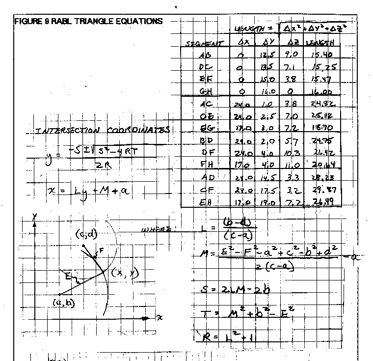
In this old example we have two points, one with coordinates a,b and the other with coordinates c,d. From point c,d we swing an arc of length F and from a,b we swing an arc of length E. Those two arcs intersect at point x,y and that is what we are looking for. The two equations in the upper left for x and y require you to solve first a bunch of factors shown in the lower right. Computers are really good at figuring this sort of stuff, even my Apple 2c would spit out the answer in a nano second.
To simplify things a bit I always chose the first two points to be one directly above the other. Well almost. In fact one can't be exactly above the other because in that case the computer will try to divide by zero when it figures the factors and it will get totally confused. So I missplace one point by .001" and the machine is quite happy to plug along.
With the Apple I would first figure the line lengths with a hand calculator as you see in the upper right of the old example, then plug the numbers into the Apple to figure the x,y coordinates of the third point of the triangle. Write that down and go on to the next triangle.
As I got more sophisticated in my used computers I eventually came up with a spreadsheet in MSworks that would do that for me up to sixteen triangles at a time. The machine works to a huge degree of accuracy and the problems of working with the drawing board all go away. Then it just becomes an issue of inputting the offsets correctly. Here is a portion of the results of the Bobsboat forward bilge panel.
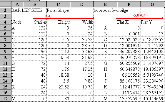
The offsets are input on the left and as you type them in the machine figures the flat panel layout on the right. If I am not using all the input spots in the spread sheet, say I have 13 triangles to plot instead of 16 allowed in the sheet, I type in convenient numbers in the blanks which sometimes results in "error" messages generated by the spreadsheet output but they are of no consequence. Then I ask for an xy chart of the results to see if it looks right, a quick check on my input. For the Bobsboat bilge panel it looks like this:
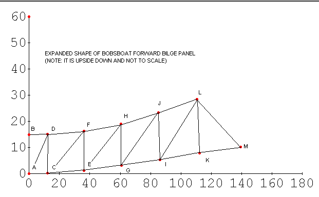
Now if you draw the xy results on your drawing board to reconstruct the triangles, and thus the true shape of the twisted panel, you will have acceptable accuracy. All of your points will be measured from the same base lines, you won't be piling errors on errors. If the input is correct, this method has always worked for me.
This method works for untwisted panels too, of course. In fact once you've got your spreadsheet down it is much faster and much more accurate than the drafting method shown last time. So in real life I use this method to figure the shapes of the side and bottom panels too. There is an interesting side idea here. Let's say on your original lines drawing you misplace or mismeasure a point such that an offset is off 1/4". If you use the above method your boat will still fit together, there will be no gap between the panels at the error location. Since all the joining panels will have been constructed to the same offsets, they will all be shaped to accommodate them including those with errors. The finished boat will of course be misshaped by 1/4" at that point but there will be no gap there between panels because of that error.
I'm quite certain that other design software such as Plyboats uses the same technique. In fact if you were flying your PC flight simulator before you read this, your smooth looking simulator aircraft was most likely an assembly of tens of thousands of little triangles. And if you were in simulated combat with maybe fifty other planes each made of thousands of tiny triangles twisting and turning as they fly atop a landscape made of a complex grid, through clouds and smoke and with tracers flashing and targets bursting into triangular bits as they are hit, all this being figured out and painted many times a second to give smooth motion. Perhaps the bomber in front of you takes a hit and bursts into flames, its crew bails out, each man an assembly of a hundred articulated triangles and as their chutes pop open you see that they are also assemblies of triangles, each panel painted a different hue according to the thoughts of your computer as it plots the rays of the setting sun over say a Dutch countryside defined to digital reality by a survey satelite ... your computer had a lot to think about!
You know what, as smart as your computer is about these things, it always is a good idea to check its thinking by making a scale model out of low tech cardboard. We'll do that next with Bobsboat in a couple of issues.
PICARA
PICARA, CABIN SAILBOAT, 18' X 7", 1300 POUNDS EMPTY
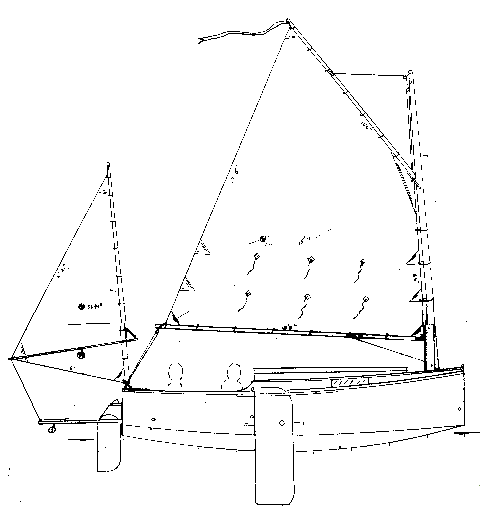
A while back I presented a design called Fatcat2 which was a 15' x 6' unballasted sailing cuddy catboat. It is still in the prototype catalog, although one was built a few years ago but never used to my knowledge. A problem with any unballasted boat is that if it capsizes it will usually lie on its side and the skipper will need to go for a swim to right the boat and then he has the problem of getting back into the righted boat.
The usual fix for that problem is to deck the boat over very well so that nothing will flood when the boat gets knocked down by the wind. (I'm reminded of Reed Smith's Rule that any boat that gets sailed a lot will eventually get knocked down.) Then ballast is added down low such that the boat's center of gravity will be "below" the boat's center of buoyancy when it is on its side. The lower the ballast, as on the end of a deep fin or keel, the less ballast is needed but of course the draft of the boat goes way up. Buoyancy up high, such as a high raised deck, also helps but there are limits to that too since the boat's CG will also be raised with it, both because of more structure up high and also because the crew weight, which often is a major contributor to a high CG, must be lifted higher so that the skipper can still see ahead over the new raised deck.
So Picara is in a lot of ways a Fatcat2 that has gone through the above changes to make it self righting, that is to say if knocked over it will right itself when the wind force is eased, with the crew staying on the deck, shedding water like a duck and being ready to go again once the crew feels up to it. (Even here the idea of "self righting" means different things to different sailors. Howard Chapelle wrote somewhere that a sharpie is selfrighting if it can return from 45 degrees of heel. I'm quite certain that is not enough for most of us. Blue water sailors try to self right from 140 degrees of heel. No, the wind won't blow you over that far but a big wave can roll you that far. On my ballasted boats, like Picara, I try to get the boat to self right from 90 degrees, a compromise I suppose, but I don't design blue water boats.)
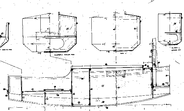
To get Picara to right from 90 degrees with two adults sitting on the aft deck requires 500 pounds of steel ballast spread flat on the deepest part of the boat's bottom in addition to using a 1" thick plywood bottom which also has about 100 pounds of ballast effect. Sound like a lot? Maybe so but the numbers kept coming up the same using Hullforms6 to figure the hydro work. I believe it. I tried it with water ballast but gave up. Steel is over eight times as dense as water so the 1-1/2" steel plate I show as ballast would be equal to a water tank over 12" deep to match the weight, but with internal ballast the water would end up centered about 6" above the bottom where the steel sits centered .75" above the bottom so the water ballast was no where near as effective here as steel. It won't work here.
Picara is 18' long where Fatcat2 was 15' in order to get a cabin that two people might really sleep in. There is a small anchor well ahead of the cabin, a raised deck aft of it, and a motor well in the stern. I used multichines to get a hull that can handle rough water better than a flattie. That makes it a taped seam project. She needs nine sheets of 1/4" plywood, six sheets of 3/8" plywood, and seven sheets of 1/2" plywood. The resulting pile of plywood would weigh about 800 pounds and I would expect the empty hull to weigh about that. Add 500 pounds of ballast and you have about 1300 pounds on the trailer. The wide deep hull can handle that and it takes a total weight of 2500 pounds to set it down 10" deep so its chines touch the water.
As for the sail rig, I used a gaff sail to get good area from a short 17' mast which pivots on a tabernacle and stows within the length of the trailered boat. I added a small mizzen for balance and provide steadying at anchor or during sail changes.
Prototype Picara plans are $30.
Prototype News
Some of you may know that in addition to the one buck catalog which now contains 20 "done" boats, I offer another catalog of 20 unbuilt prototypes. The buck catalog has on its last page a list and brief description of the boats currently in the Catalog of Prototypes. That catalog also contains some articles that I wrote for Messing About In Boats and Boatbuilder magazines. The Catalog of Prototypes costs $3. The both together amount to 50 pages for $4, an offer you may have seen in Woodenboat ads. Payment must be in US funds. The banks here won't accept anything else. (I've got a little stash of foreign currency that I can admire but not spend.) I'm way too small for credit cards.
I think David Hahn's Out West Picara is the winner of the Picara race. Shown here on its first sail except there was no wind. Hopefully more later. (Not sure if a polytarp sail is suitable for a boat this heavy.
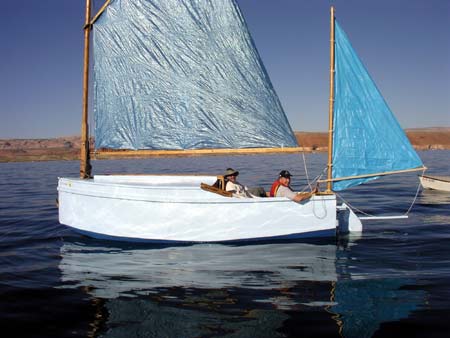
Here is a Musicbox2 out West.
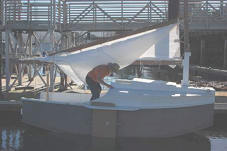
This is Ted Arkey's Jukebox2 down in Sydney. Shown with the "ketchooner" rig, featuring his own polytarp sails, that is shown on the plans. Should have a sailing report soon.
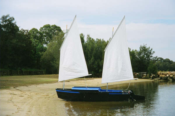
And the Vole in New York is Garth Battista's of www.breakawaybooks.com, printer of my book and Max's old outboard book and many other fine sports books. Beautiful job! Garth is using a small lug rig for sail, not the sharpie sprit sail shown on the plans, so I will continue to carry the design as a prototype boat. But he has used it extensively on his Bahamas trip towed behind his Cormorant. Sort of like having a compact car towed behind an RV.

And a Deansbox seen in Texas:
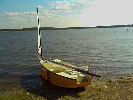
Another prototype Twister is well along:
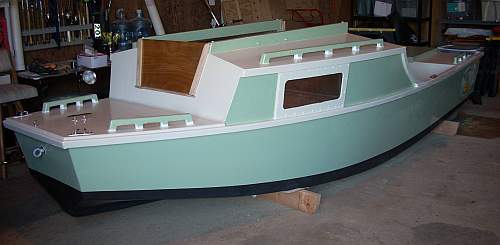
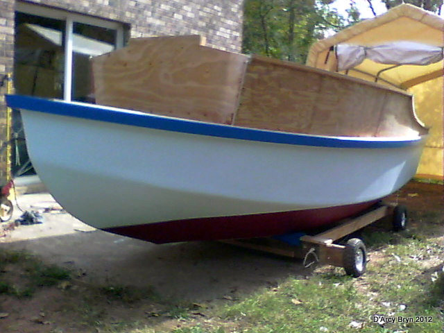
And the first D'arcy Bryn is taped and bottom painted. You can follow the builder's progress at http://moffitt1.wordpress.com/ ....
AN INDEX OF PAST ISSUES
A NOTE ABOUT THE OLD WAY BACK ISSUES (BACK TO 1997!). SOMEONE MORE CAREFUL THAN I HAS SAVED THEM. TRY CLICKING ON...
which should give you a saving of the original Chuck Leinweber archives from 1997 through 2004. They seem to be about 90 percent complete.
BACK ISSUES LISTED BY DATE
Hullforms Download (archived copy)
Brian builds Roar2 (archived copy)
Herb builds AF3 (archived copy)
Herb builds RB42 (archived copy)