BACKGROUND...
If you look at the picture below of the sail rig of Mayfly12 you will
see on the sail some (fuzzy) writing (that didn't scan well) that
says "55 square feet" to the left of a small circle that represents
the center of that area (honest).
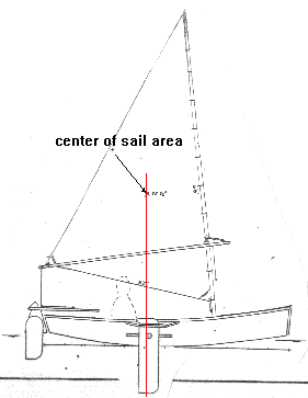
The center of that area is often called a "centroid" and you will see
it is placed more or less directly above the center of the leeboard's
area. That is very important.
As you might imagine a shallow flat hull like this with a deep narrow
leeboard wants to pivot around that leeboard. If the forces of the
sail, which in a very general way can be centered at the sail's
centroid, push sideways forward of the leeboard, the boat will tend
to fall off away from the wind. You should be able to hold the boat
on course with the rudder but in that case the rudder will have "lee
helm" where you have to use the rudder to push the stern of the boat
downwind. The load on the rudder will add to the load of the
leeboard. Sort of a "two wrongs make a right" situation and generally
very bad for performance and safety in that if you release the tiller
as you fall overboard the boat will bear off down wind without you.
If the centroid is aft of the leeboard you will have "weather helm",
a much better situation. The rudder must be deflected to push the
stern towards the wind and the force on it is subtracted from the
load on the leeboard. Not only that, but when you release the tiller
as you fall overboard the boat should head up into the wind and stall
and wait for you if you are lucky. It's a good deal but if you overdo
it you can end up with too much load on the rudder.
This balance problem is actually one of the few things about sail
rigs that is not arbitrary. The type of rig and its area are pretty
arbitrary depending on how fast you want to go, how much you weigh,
etc. But balance is quite important and is one of the areas where
backyard boaters get into trouble, sometimes changing the boat or rig
with no thought of balance. So before you go doing that you should do
a little homework. This essay will tell you how to figure sail area
and find the centroid.
One last item: the balance situation shown for Mayfly12 is what I
have found to be best for this type of boats. Boats with large fin
keels don't balance that way - usually the sail centroid is well
forward of the keel centroid. That distance is called the "lead".
That type of boat is not within my personal experience and I'm not
going to get into that. But you still would have to figure the area
and centroid.
THREE SIDED SAILS...
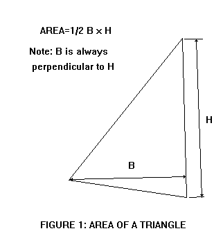
This one is really easy. The area is just the base time the height
divided by 2. Any side can be the base and the height is aways at a
right angle to the base.
So when you lay out the sail you draw it up on thin paper to the same
scale as your hull drawing with the leeboard (or daggerboard or
centerboard) lowered. Draw a line through the center of the board
straight up. Now we're going to locate the scale sail on the boat
such that it's centroid falls very close to that line.
Here's how you find the centroid of a triangular sail.
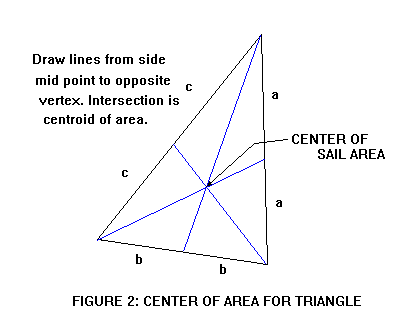
Find the midpoint of each side and and draw a line from that midpoint
to the vertex opposite it. The three lines will intersect at the
centroid. Actually you only need to find the intersection of two
lines but the third line is a good check.
That's it! Now you can take you scale sail drawing and slide it
around your hull drawing until the centroid is on that line drawn up
from the hull's board. Move it up and down and tilt it until you like
the way it looks. But don't cheat much forward or aft of that line.
FOUR SIDED SAILS...
To find the area of a four sided sail you just divide it into two
triangles, find the area of each triangle as above, and add the two
together.
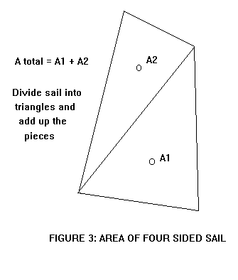
Now to find the centroid of the four sider. Start by finding the
centroids of the two triangles that make up the four sided sail as
shown above. Now draw a line from one triangle centroid to the other.
The centroid of the four sider is on that line somewhere.
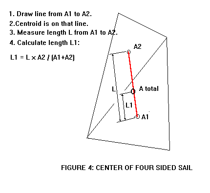
To find exactly where the centroid is on that line, measure the
length of that connecting line. You need not use the same scale as is
used on the drawing. I prefer to use a millimeter scale for this
measurement. Then get out the calculator and work the formula shown
in the Figure 4. Let's say for example the length of the connecting
line on the scale drawing measures 120 mm (that is measurement L).
Let's say the example sail has a lower triangle area of 50 square
feet (that is A1). The upper triangle is 35 square feet (that is A2).
So the total sail area is 50 + 35 = 85 square feet. The length L1,
which will exactly locate the sail's total centroid, is L1 = 120 x
35/85 = 49.4 mm. So you take that millimeter scale and measure up
from A1 centroid on the connecting line 49.4 mm and make a tick mark
on the connecting line. That is the centroid of the total sail.
Another way to find the centroid, especially of a really odd shaped
sail, is to take the scale drawing of the sail and cut it out. Then
balance the cutout on a knife edge and mark the balance line, rotate
the cutout on the knife edge about 90 degrees and rebalance and mark
the new balance line. The centroid lies at the intersection of the
two line.
Another way is to dangle the cutout on a pin stuck through a corner
and into a wall marked with a vertical line that passes through the
pin point. Mark the line that passes through that pivot corner and a
vertical. Then rotate the cutout to hang it from another corner, and
mark a second line through the second pivot corner and a vertical.
The centroid lies at the intersection of those two lines. Back at the
missle factory the designers had a favorite place, complete with
pivot pin socket hole and vertical line, to hang these cutouts and
that place was known as the "weighing wall". Meanwhile the super
computer cranked away next door but its answers weren't to be trusted
unless they agreed with the cutout hanging at the weighing wall.
RIGS WITH MANY SAILS...
Figure 5 shows the rig for Viola22. It has a main gaff sail of 177
square feet, and a mizzen sail of 45square feet. Where is the
centroid of the assembly?
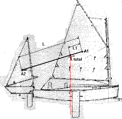
It's done exactly as with Figure 4. Draw a line connecting the areas
of the two sails. Measure the length of the connecting line. Then run
through the same equation as in Figure 4. Nothing to it.
One thing I might point out about the Viola22 rig is that the total
centroid falls near the aft edge of the leeboard. By my experience
the mizzen is not as efficient as its area suggests so it needs to be
a bit oversized by normal rules, fudging the total centroid aft. I
think in general the aft sails operate in the scrambled flow of the
forward sail, causing loss of force back there.
Contents
Caprice
CABIN SAILBOAT, 25' X 6', 900 POUNDS EMPTY
About 15 years ago I built a Payson Canoe and used it for several
years before selling it. I replaced it about 10 years ago with my
Toto double paddle canoe. Toto has the same multichine cross
section as the Payson Canoe but I tried for a long lean bow which
would be better in rough water and more foregiving of bow down
trim. I still have that Toto, unchanged in any way since new, and
still use it all summer. Amanda Johnson demonstrates:
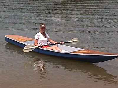
The Toto shape worked so well that I used it in other designs like
Roar2 and RB42. I tried it also in a sailing boat, the 20' Frolic2
(the original Frolic was narrower, more of a rowboat than a
sailboat). Frolic2 was unballasted with a small cuddy and I hoped
it would be a good daysailer and one man camping boat.
Bill Moffitt had built my Woobo design and funded a 20% enlargement
of Frolic2 that would have a cabin, water ballast, and a yawl rig
for cruising near the Gulf Coast.
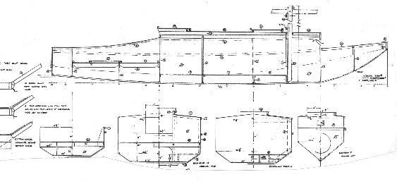
The 20% enlargement idea went very well except that I had to deepen
the hull more than that to give some serious headroom in the cabin,
but it doesn't have standing headroom. Great empasis was placed on
ease of use and rigging. The main mast is short and stepped in a
tabernacle. There is a draining anchor well in the bow, a small
storage segment under the front deck. The mast tabernacle is bolted
to the bulkhead that forms the front of the sleeping cabin. There
is a utility room aft of the sleeping room. Water ballast tanks are
under the bunks and in the sides of the utility room floor, about
600 pounds of ballast as I recall. Aft of the cabin is the self
draining raised cockpit with storage volume under the deck. Finally
there is a self draining motor well across the stern. Construction
is taped seam plywood.
Bill couldn't start his Caprice right away but Chuck Leinweber of
Duckworksmagazine
gave it a try. He has the room and tools and smarts to tackle a
project like this with no hesitation. There weren't many changes
from the plans that I know of, the main one being adding a
conventional footwell to the aft deck which is designed to have a
hatch type of foot well as with the Bolger Micro.
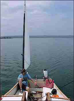
Chuck trailered his Caprice up from Texas to our Midwest Messabout
this June and I had a chance to go over it, sail it for a couple of
hours, and watch it sail from other boats. Wonderful!
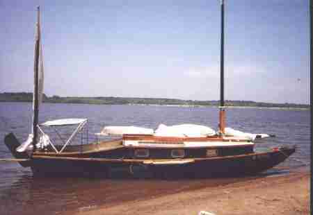
Chuck tells me it takes less than 15 minutes to rig the boat to as
you see here. As shown the boat has its ballast so you see it
beaches very well indeed. I asked about the ballast. He can flood
the tanks without power, just open the access plate, reach in and
pull the fill plug and let the water rush in. Since the tops of the
tanks are about even with the normal waterline he has to move his
weight around to keep the tank depressed long enough to completely
fill. Then you reach into the filled tank, replace the plug in the
bottom, and then replace the access plate in the top. There are two
tanks to fill.
Are the ballast tanks worth the building effort? On a multichine
hull like this the tops of the tanks form flats that give places
for bunks and storage so that is good. When full the boat should
have a very good range of stabiltiy. Chuck's boat has never been in
rough going as I'm writing this so the effect of the ballast
remains to be proven. It has been capsized in a practice but the
ballast tanks were empty and the boat was empty with no crew, etc..
But the ballast is a success from the standpoint that Chuck is able
to tow his Caprice behind a four cylinder pickup truck. My idea was
to pull the boat up the ramp and drain the tanks afterward by
simply pulling the drains plugs. But Chuck has found it best by far
to empty the tanks before recovering the boat at the ramp. So he
uses a bilge pump in each tank to pump them empty. I'd be worried
about water ballast tanks on a wooden boat from a rot standpoint
and would be careful to open all the plugs and access panels when
the boat is stored.
(I should add that I think an empty Caprice will weigh about 900
pounds based on the plywood sheet count (eight sheets of 1/4", nine
sheets of 3/8" , five sheets of 1/2" and one sheet of 3/4"). But
any boat like this can hold an awful lot of gear and junk.)
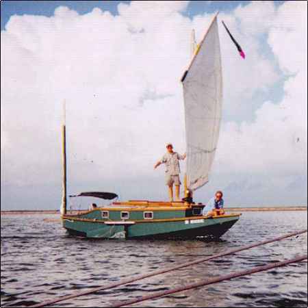
Caprice has the tabernacle setup that I first saw on Karl James'
sharpie. The mainsail is 190 square feet, balanced lug. The mast is
fairly short, stowing within the length of the boat when lowered.
Chuck demonstrated putting up the mast, maybe a 15 second
operation. I've been drawing these for a while on different boats
but this is the first one I know of to get built and used. I'm
greatly relieved that is all works so well. Before you decide to
tack a tabernacle like this onto your boat, be advised that the
tabernacle posts go clear to the hull bottom with big bolts all
around a beefy bulkhead.
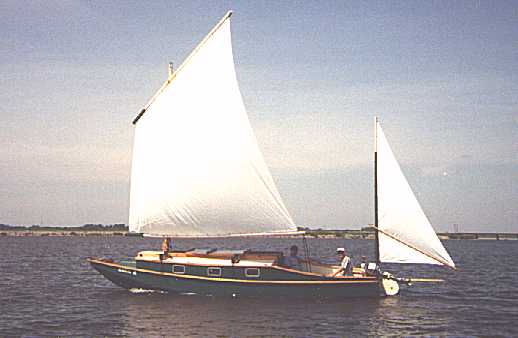
I thought Caprice sailed very well in the light winds we had that
weekend. Tacked very smoothly through 90 to 100 degrees which is
all you can ever get with a low tech rig. Very smooth and quiet
compared to the sharpies I'm used to. It didn't seem at all
sensitive to fore-aft trim. In the light winds it went 5 knots on
the GPS which is certainly fast for the conditions.
Well, all in all I thought Caprice was everything I was hoping
for.. Plans are $45.
Contents
Prototype News
Some of you may know that in addition to the one buck catalog
which now contains 20 "done" boats, I offer another catalog of 20
unbuilt prototypes. The buck catalog has on its last page a list
and brief description of the boats currently in the Catalog of
Prototypes. That catalog also contains some articles that I wrote
for Messing About In Boats and Boatbuilder magazines. The Catalog
of Prototypes costs $3. The both together amount to 50 pages for
$4, an offer you may have seen in Woodenboat ads. Payment must be
in US funds. The banks here won't accept anything else. (I've got
a little stash of foreign currency that I can admire but not
spend.) I'm way too small for credit cards.
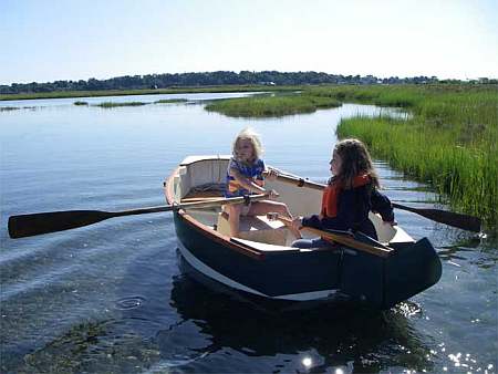
I think David Hahn's Out West Picara is the winner of the Picara
race. Shown here on its first sail except there was no wind.
Hopefully more later. (Not sure if a polytarp sail is suitable
for a boat this heavy.
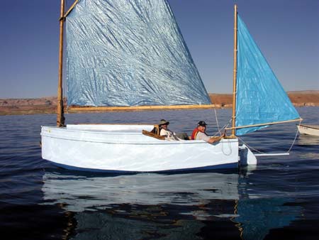
Here is a Musicbox2 out West.
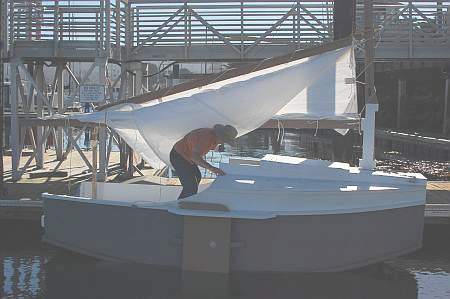
This is Ted Arkey's Jukebox2 down in Sydney. Shown with the
"ketchooner" rig, featuring his own polytarp sails, that is shown
on the plans. Should have a sailing report soon.
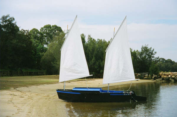
And the Vole in New York is Garth Battista's of
www.breakawaybooks.com, printer of my book and Max's old outboard
book and many other fine sports books. Beautiful job! Garth is
using a small lug rig for sail, not the sharpie sprit sail shown
on the plans, so I will continue to carry the design as a
prototype boat. But he has used it extensively on his Bahamas
trip towed behind his Cormorant. Sort of like having a compact
car towed behind an RV.
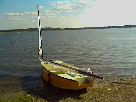
And a Deansbox seen in Texas:
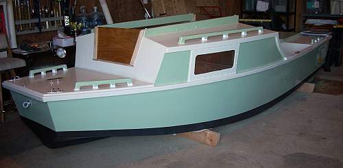
Another prototype Twister is well along:
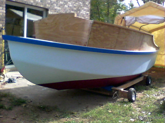
And the first D'arcy Bryn is taped and bottom painted. You can
follow the builder's progress at http://moffitt1.wordpress.com/
....
Contents
AN INDEX OF PAST ISSUES
THE WAY BACK ISSUES RETURN!
MANY THANKS TO CANADIAN READER GAETAN
JETTE WHO NOT ONLY SAVED THEM FROM THE 1997 BEGINNING BUT
ALSO PUT TOGETHER AN EXCELLENT INDEX PAGE TO SORT THEM
OUT....
THE WAY BACK ISSUES
SOME
LINKS
Mother of All Boat
Links
Cheap Pages
Duckworks
Magazine
The Boatbuilding
Community
Kilburn's Power
Skiff
Bruce Builds
Roar
Dave
Carnell
Rich builds AF2
JB Builds
AF4
JB Builds
Sportdory
Hullforms Download (archived copy)
Puddle Duck
Website
Brian builds Roar2 (archived copy)
Herb builds AF3 (archived copy)
Herb builds RB42 (archived copy)
Barry Builds
Toto
Table of Contents
