Jim Michalak's Boat Designs
1024 Merrill St, Lebanon, IL 62254
A page of boat designs and essays.
(1 April 2022) We discuss sailing spars. The 15 April issue will look at water ballast.
ORDER NEWS
THE BOOK IS OUT!
BOATBUILDING FOR BEGINNERS (AND BEYOND)
... is out now, written by me and edited by Garth Battista of Breakaway Books. You might find it at your bookstore. If not check it out at the....
ON LINE CATALOG OF MY PLANS...
...which can now be found at Duckworks Magazine. You order with a shopping cart set up and pay with credit cards or by Paypal.
ALSO...In addition to the Duckworks downloads I also now have access to a large format inkjet printer which is making very nice full sized prints on paper. So I can return to what I started 30 years ago, you order direct from me by snail mail using the address above only with cash or check in US funds with the prices shown on this website, and I mail you full sized 2'x 3' paper prints. The price includes first class mail to US and Canada.
SAIL RIG SPARS
I'll contiune the "sail thoughts" that I started a while back. This time will discuss the actions of spars a bit, especially with a look at deflections of spars used in simple homebuilt rigs and how they affect some things the sailmaker might do
Figure 1 shows an idealized version of the spars of a balanced lug rig. Here I've assumed that all of the halyard load is transmitted through the luff and leach of the sail. That's not totally true but in a well cut sail only the luff and leach will be tight if the wind isn't blowing because the sail is cut to have a loose pocket of draft in its center. But when the wind starts blowing the entire sail developes tension and the yard and boom are loaded by that cloth along their length. Anyway, I've shown the halyard with a nice round 100 pound load. What are the deflections of the yard and boom?
Figure 2 shows how to figure the deflection of a beam loaded as in Figure 1. The source of the equation is a book called Roark's Formulas For Stress and Strain. That book is a super cookbook for the stress analyst, the stressman's bible.
I think most of the elements of the formula are plain except for the "EI". E in an equation that predicts deflection is alway the modulus of elasticity, pretty much a spring rate for the material and it has units of "pounds per square inch" and has nothing to do with the strength of the material, only its stiffness.. It's a very large number. For aluminum E is 10 million. For wood E is about 1.5 to 2 million The length dimension "a" is always from the load "W" to the nearest end of the beam.
The "I" in the equation is the moment of inertia of the cross section of the spar. It has units of "inches to the fourth". Figure 3 shows how to figure the moment of inertia for square cross sections and round cross sections. As you see the I of both the square and round sections are related to the fourth power of the thickness of the section so a little increase in thickness gives a big increase in moment of inertia and thus in stiffness. For example a 1" diameter boom has an I of .05. A 1.5" diameter boom will have an I of .24. And we have increased the bending stiffness by a factor of 5! By the way, if you have a hollow spar, the I can be figured simply by taking the I of the OD of the tube and subtracting the I of the ID of the tube. For example, a round tube of 1.5" OD and 1" ID would have an I of .24 - .05 = .19. So the tube is almost 4 times as stiff as the 1" solid spar but only 26% heavier. So tubes are popular with those who can afford them.
Now, if you crank through all the equations for the yard assuming the yard is of wood and has a cross section of 1-1/2" square you will find the yard will flex over 3" under the 100 pound halyard load. (Actually the work was done with an applied load W = 70 pounds because the yard is tilted 45 degrees and only a 70 pound component of the 100 pounds is acting perpendicular to the beam.) So what?? It's actually a big deal to the sail maker. If you recall the essay on sailcloth you might remember that a sail 10' wide with a 1' draft will actually have an arc length of about 10' 2-1/2" across its middle. So the sailmaker will sew in the extra 2-1/2" to supply the draft. That might appear as a bulge of 1-1/4" along both the foot and head of the sail. So if the yard and boom are straight, the proper amount of draft will appear in the center of the sail. But if the yard flexes 3" under the sail load, it will pull all the draft out of the sail! So one of the problems the sailmaker has to face is to guess at the flexing of the rig. In this case he might supply the head with 3" + 1-1/4" = 4-1/4" of curve at the head of the sail.
But then again he may not supply that much and here is why. One nice thing about a lug rig with a flexing yard is that as shown above the flexing will pull draft out of the sail when a large sail load is applied. In many cases that might be considered to be good because it will flatten the sail in high winds. On the other hand, if you feel your lug sail does not have enough draft in high winds, one thing you could try to cure the situation might be to increase the size of the yard.
If you run the numbers for the boom, assuming the same 1-1/2" square section, you will find the flexing is small compared to that of the yard, about 1/2". That's mostly because the boom is shorter and because it is supported closer to its ends, near where the loads are being introduced. In fact it is possible that the boom will flex towards the sail under a large load and add draft to the sail in high winds.
Figure 4 shows a free standing sharpie sprit rig. The sail of a sharpie sprit can be pretensioned by tightening up the snotter which is the tackle on the mast end of the sprit boom. How much will the mast flex?
Let's say the mast here has a 2" square cross section. And let's say the snotter tackle is a 2 to 1 thing so that the skipper pulls on the rope with a 50 pound tug and it results in a 100 pound preload on the sprit boom. The boom is in compression. You can imagine the mast deflecting under the load like a bow and arrow. Crank through the equations and it turns out the mast will flex over 3", assuming the mast is 2" square from top to bottom.
But few masts are made that way. Almost all are tapered and the taper greatly affects the deflection. As above, the sailmaker needs to know the deflection so he can allow extra material in the form of a bulge on the luff that anticipates the flex of the mast. Jim Grant of Sailrite kits recommended that the sailmaker predict the flex allowance of an unstayed mast by placing the mast on sawhorses and place a weight equal in pounds to 1/3 the sail area in square feet at the center of the mast. Then you stretch a line along the mast and measure to it a various stations along the mast and make a plot of the mast flex. Then that flex is added to the draft allowance of the sail at the luff. Usually the flex allowance is a lot more than the draft allowance!
WHAT I THINK IT ALL MEANS....
To put this all into perspective, I doubt if anyone except a Cup boat has the resources to do a meaningful analysis of the deflections of the spars of the boat. Even then, I would not trust the results of a paper analysis unless it was backed up by a wealth of real life experirence. There are so many variables. But for us little sailors it is worth while to get a handle on how much the rig is flexing and what effects the flexing is having on the set of the sail.
River Runner
RIVER RUNNER, FLOAT BOAT, 15-1/2' X 45" X 100 POUNDS
This was a custom project for a man who wanted a Lowe Paddlejon boat but found they were quite rare, essentially a custom order. The idea of a boat like this is to float mild rivers with a guide in the stern directing with a paddle and a passenger or two up front fishing. You might recall the design I did last year called Ozarkian which is very similar, maybe the father or grandfather of the Lowe design. (I suspect southern Missouri is sort of jonboat heaven, the source of most of them both in spirit and in material. I recall driving the interstate down to Springfield, Mo. about ten years ago and near Lebanon, Mo I passed what seemed to be miles of aluminum jonboats and pontoon boats stored in fields along the highway. Even little children there must know how to weld aluminum.)
He sent me some photos of a paddlejon he had seen recently and a sales brochure. I tried to copy the lines, thinking all the time that these boats are a lot more subtle than you might think. At the time I had no real Lowe around to study but the brochure left me with the impression that the paddlejon was perhaps a regular small power jon made long and double ended with swept up lines both fore and aft to allow easier paddling. But it is not quite a true double ender in that the stern transom is raked for the usual 15 degree motor mount. As far as power goes, a boat like this won't plane nicely at all, trying to stand on its stern at the least excuse, so I say 3 hp max.
Getting back to the lines, I had the feeling that these are made from a constant width piece of aluminum, say 32" wide on the bottom and 16" wide for each side for a total panel width of about 64". Stiffening wales are already pressed into the panel. The flat wide panels are folded with a brake such that the proper flare of the sides is established. The end chines are notched and the end bottoms drawn up and the end sides are drawn in to close the notches which are then welded shut. But the chines for the main portion of the hull are not welded at all, just bent. There seems to be another trick in that the top of the sides bends inward a lot sooner than does the bottom of the sides, resulting in a rolling flare that gives the boat a somewhat elegant shape (I think). So you might think a manufactured jonboat is a dumb and brutish thing, but I'm quite certain most of them are actually pretty clever.
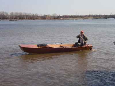
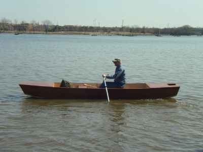
Jim Hauer built the prototype in Green Bay and sent these photos. I think it came out exactly as hoped. Remember, this is not really a rowing boat as much as a floating boat so the face forward rowing will be used more to steer than to propel. The photo of the man paddling in the stern shows that the aft transom is still up giving good flow lines there, unlike a square stern power jonboat. Under power Jim said that 2.5 hp is about all you can take, the boat not behaving well above that.
Anyway, River Runner uses five sheets of 1/4" plywood. The idea of the light ply is to keep the boat light enough to manhandle into a truck or onto a car roof but it will take a diligent builder to keep it light. I suspect the aluminum original would be no heavier. Simple nail and glue construction.
River Runner plans are $20 when ordered direct by mail from me.
Prototype News
Some of you may know that in addition to the one buck catalog which now contains 20 "done" boats, I offer another catalog of 20 unbuilt prototypes. The buck catalog has on its last page a list and brief description of the boats currently in the Catalog of Prototypes. That catalog also contains some articles that I wrote for Messing About In Boats and Boatbuilder magazines. The Catalog of Prototypes costs $3. The both together amount to 50 pages for $4, an offer you may have seen in Woodenboat ads. Payment must be in US funds. The banks here won't accept anything else. (I've got a little stash of foreign currency that I can admire but not spend.) I'm way too small for credit cards.
We have a Picara finished by Ken Giles, past Mayfly16 master, and into its trials. The hull was built by Vincent Lavender in Massachusetts. There have been other Picaras finished in the past but I never got a sailing report for them...
And the Vole in New York is Garth Battista's of www.breakawaybooks.com, printer of my book and Max's old outboard book and many other fine sports books. Beautiful job! Garth is using a small lug rig for sail, not the sharpie sprit sail shown on the plans, so I will continue to carry the design as a prototype boat. But he has used it extensively on his Bahamas trip towed behind his Cormorant. Sort of like having a compact car towed behind an RV.
And a Deansbox seen in Texas:
Another prototype Twister is well along:
A brave soul has started a Robbsboat. He has a builder's blog at http://tomsrobbsboat.blogspot.com. (OOPS! He found a mistake in the side bevels of bulkhead5, says 20 degrees but should be 10 degrees.) This boat has been sailed and is being tested. He has found the sail area a bit much for his area and is putting in serious reef points.
AN INDEX OF PAST ISSUES
THE WAY BACK ISSUES RETURN!
MANY THANKS TO CANADIAN READER GAETAN JETTE WHO NOT ONLY SAVED THEM FROM THE 1997 BEGINNING BUT ALSO PUT TOGETHER AN EXCELLENT INDEX PAGE TO SORT THEM OUT....
THE WAY BACK ISSUES
15apr21, Water Ballast, Mayfly16
1may21, AF3 Capsize, Blobster
15may21, Mast Tabernacles, Laguna
1jun21, Underwater Boards, QT Skiff
15jun21, Capsize Lessons, Mixer
1jul21, Scarfing Lumber, Vireo14
15jul21, Rigging Lugsails, Frolic2
1aug21, What Is Horsepower, Oracle
15aug21, Sharpie Sprit Sails, Cormorant
1sep21, Measuring Prop Thrust, OliveOyl
15sep21, Leeboard Issues, Philsboat
1oct21, Sizing Underwater Boards, Larsboat
15oct21, Choosing A Design, Jonsboat
1nov21, Lugsail Jiffyreef, Mayfly14
15nov21, Sharpie Sprit Reef, Piccup Pram
1dec21, Junk Rig Test, Ladybug
15dec21, Taped Seams , Sportdory
1jan22, Rowboat Setup , Normsboat
15jan22, Sail Area Math , Robote
1feb22, Bulkhead Bevels , Toto
15feb22, Trailering Boats , IMB
1mar22, Small Boat Rudders , AF4Breve


