Jim Michalak's Boat Designs
1024 Merrill St, Lebanon, IL 62254
A page of boat designs and essays.
(1 June 2020) We discuss underwater boards. The 15 June issue will be about capsize recovery.
THE BOOK IS OUT!
BOATBUILDING FOR BEGINNERS (AND BEYOND)
... is out now, written by me and edited by Garth Battista of Breakaway Books. You might find it at your bookstore. If not check it out at the....
ON LINE CATALOG OF MY PLANS...
...which can now be found at Duckworks Magazine. You order with a shopping cart set up and pay with credit cards or by Paypal. Then Duckworks sends me an email about the order and then I send the plans right from me to you.
REND LAKE 2020...CANCELLED!!
..I see no way that any gathering will be safe by mid June, at least not in southern Illinois. First miss in over 30 years, but we will be back next year.
 | Left:
Norm Wolfe's tabernacle on his Raider. He writes, "Raider has a tabernacle mast and it works great. The mast is a 6 meter fiber glass flag pole with a 1 meter steel sleeve inside which I left inside as a counterbalance. Takes about 5kg of force to raise! Long steel bolt at the foot holds it up." And he stows his paddle there too! |
|
Underwater Board Shape
Aircraft designers have been trying to predict the performance of wings since the very beginning. The Wright brothers not only developed the airplane but made some of the best wind tunnels of their time. And from the very beginning they noticed that long skinny wings usually performed better than short fat ones. And so it is with the underwater board of a sailboat. In its own way it "flies" through the water producing a force that counteracts the side loads produced by a fore-and-aft sail rig.
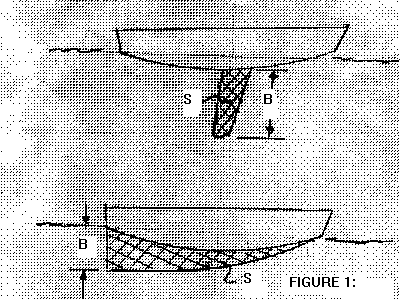
Designers quickly developed the term "aspect ratio" to measure that feature of a wing. The aspect ratio of an underwater board is AR=2 x B x B / S, where B is the length of the board and S is its area. Figure 1 shows how you measure those elements. (Aero students will note that the above equation is twice the usual given for an aircraft wing which has two tips while an underwater board has but one tip.)
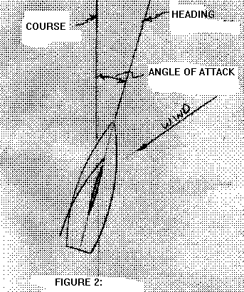
Next, for a board with a symmetrical cross section (so it can function equally on all tacks), the board must go through the water at an "angle of attack" to generate force, as we discussed in the last issue. Figure 2 shows how the situation applies to a close hauled sail boat. The skipper wants to go to on a certain couse but because of the angle of attack required by the board he must head his boat upwind by the angle of attack. So he might think the boat is "slipping" and producing "leeway" equal to the angle of attack. One other important thing to notice here is that any angle of attack of the underwater board must subtract from the angle of attack of the sails. A bad situation. Sort of a double penalty.
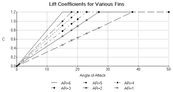
Now look at Figure 3. Here is the big message: High aspect ratio boards (deep and skinny) reach their lift coefficients with less angle of attack than do shallow fat boards. The figure is sort of idealized but Marchaj gives examples of tests of different actual boards that agree with the figure.
Low aspect ratio keels can be successful if they have sufficient area to allow them to always operate at a low C. The Micro has I think about 14 square feet of keel, about twice the value I recommended of 4% of the sail area for a deep skinny fin. Large low aspect ratio keels also make for steadier boats. Marchaj points out that they have superior damping which makes for a safer boat in rough going.
As an example, let's use Frolic2 again. Her board has 4.4 square feet of area immersed and it is 3.5 feet deep. So the aspect ratio is 2 x 3.5 x 3.5/ 4.4 = 5.6. Now let's say we wanted to guess at leeway on a close reach in 10 knots wind, and we'll assume she is going 4 knots at the time. Frolic2 has 114 square feet of sail and 10 knots produces about .5 psf on a typical good sail, so that is 57 pounds of sail force. We'll assume that all of that force is counteracted by the board. So the overall pressure on the board is 57/4.4 = 13 psf. Now we need to calculate the value of C for the fin. Remember that the psf on the fin is = 2.86 x V x V x C. Using V = 4 knots, we can solve for C and get C = .28. Now get into the aspect ratio figure, guess where AR = 5.6 might be and it appears that the leeway angle would be about 4 degrees.
Here's an interesting "what if". What if the Frolic2 narrow board were instead mounted like a shallow keel such that it still has 4.4 square feet of area but now has a length of 3.5 feet and a depth of 1.25 feet? Now its aspect ratio = 2 x 1.25 x1.25 / 4.4 = .71. Going into the aspect ratio chart you would see the leeway for this fin would be about 15 degrees under the same situation.
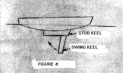
Let's get one step fancier and say we have the original board set up as a centerboard that folds into a similar sized shallow stub keel as shown in Figure 4. This is a pretty common arrangement. Now the two areas will share the side load, but in what proportion? One thing we can say is that they will operate at the same angle. Let's guess that the angle of attack is 4 degrees. Then the deep skinny board is operating at a C of about .3 while the shallow fat board is operating at a C of about .1. They have the same area so the deep skinny board is producing three times the lift of the stub keel! It's doing nearly all the work. And it will continue to do so until the angle of attack reaches about 15 degrees at which point the deep skinny board reaches C max of about 1.2. Then the stub keel is working at a C of about .3 and will continue to be effective until it reaches an angle of maybe 50 degrees. You wouldn't want to sail at a 50 degree leeway angle although there might be times when it would be advantageous. I can't really think of such a situation.
I suppose the reason I am writing this is as a warning to those who just want long boards on edge instead of deep blades. The question comes up all the time, over and over. In a general way I can say with confidence that I have never seen a shallow hull built with long shallow board on edge type keels sail well in the sense of going to windward well or being able to maneuver quick and sure. It might work well for long downwind stretches. I have written about meeting Matt Leyden who has been using "chine runners" which don't even project below the bottom. But his boats are supposed to be ballasted to float much more deeply than you might expect from a small simple plywood hull. For example a hull 4' wide would need at least 1' of draft. So they have a lot of side area under the water and most likely the chine runner is primarily to reduce harmful flow swirling around the chine. And he uses deep draft rudder blades and maybe his sail areas are aft enough to carry sail side loads somewhat with the rudder.
QT Skiff
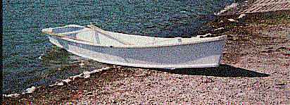
LIGHT ROW SKIFF, 13' X 45", 75 POUNDS EMPTY
QT SKIFF
Paul Krayniak of Odessa, NY, built the prototype QT, his first boat, in a couple of weeks. Here is the letter he wrote me:
"Hi Jim,
Building Qt was very easy and a great learning experience. I have read Payson's books, so there were no real surprises in this project. As you know, I mostly used hand tools, and really didn't need much else, though the oar I built with a belt sander was quite a revelation. I used a rasp, handsaw and plane which were my grandfather's, so that added something to the experience. Altogether, including making oars and painting, I spent about 60 hours abuilding. I used polyurethane glue, which worked fine, but makes a real mess when it expands into foam, and costs more than epoxy. She was painted with alkyd porch and deck enamel, which gives a very nice finish and should be extremely tough (according to the salesperson). The plywood was AC exterior, the other wood was yellow pine. If I were doing this project again, I would use fir instead of pine, the Weldwood glue as recommended by you, and latex paint since the alkyd takes a long time to cure. Also, I think Grandfather's memory has been honored enough, and I would use a table saw and a belt sander for sure.
When I took QT to the water for her first trial, it was quite windy and I hadn't rowed for many years, so our path was pretty erratic. For the next trial, I adjusted the oarlock position up the oars an inch, moved their pivots two inches astern and adjusted my seat to get the level oars at belly button height, per your instructions. It was still pretty windy but the rowing went much better. The next time out, the wind was calm and we went for quite a long way, about 5 miles. I was very impressed with the small rowing effort required with this boat, and we covered the distance easily in about an hour and a half.
This testing was all done with my wife and me aboard. As I mentioned to you before, we are both big people. Frankly we had some doubts about quarter inch plywood holding us up, but it seems very sturdy and tolerates us walking on the bottom just fine. Also, we are able to change places and otherwise move around in her OK.
We tried putting our 70 pound grandson in with us and it didn't work well. If he sat in the back, the drag increased noticeably, and if he sat in the front, the stem was immersed and the drag was bad. Our impression was that she does best, given the limited places to sit, with two people of about the same size aboard. I'm sure, though, that all boats need to be balanced to do best.
The project has been loads of fun and the most satisfying thing I've done for years. Thanks.
Paul"
Later Paul reminded me that the idea behind his QT was first to have a boat to carry atop his motorhome.
He added, "QT fits very well on our motorhome. I made a simple bow holder from a short piece of 2x6 bolted flat to the roof. It has an outline of the wales routed into it, and I just hook the bow gusset over it. With lines running from eyebolts in the 2x6 to an eyebolt through QT's stem, it ain't going anywhere. The stern is fastened with lines down to the bumper braces and tied to the ladder to prevent lateral movement. The oars fit nicely with my fishing poles in a 10 inch square compartment which goes all the way across the motorhome. My wife and I can have her ready to travel or row in 5 minutes."
Well Paul certainly did an excellent job. One comment about his experience. Trimming you and your boat for level operation is very important as he points out. Always take the time to do it. I always give oarlock locations on my drawings but they are just suggestions and don't be shocked if you have to tinker with them to get the boat right. Often you can't tell if the boat is trimmed right without having an observer dockside to advise. If you are rowing solo or with passengers, you will need separate oarlocks for each configuration. When Paul tried to row with his grandson making a crew of three, it didn't work because the boy's weight ended up in the boats ends and threw off the trim. The usual solution would be to put the boy between the two adults, in the middle of the boat. But QT may not really be big enough for three, she's only 13' long.
The QT plans also included a page of the same hull set up for a small motor, say 5hp max. Eventually one got built by Barron Wester. He he goes...

So you get both the rowing plans and the powerboat plans in the same packet. This is a simple nailed together job from three sheets of 1/4" plywood. No jigs, no lofting.
Plans are $25.
Prototype News
Some of you may know that in addition to the one buck catalog which now contains 20 "done" boats, I offer another catalog of 20 unbuilt prototypes. The buck catalog has on its last page a list and brief description of the boats currently in the Catalog of Prototypes. That catalog also contains some articles that I wrote for Messing About In Boats and Boatbuilder magazines. The Catalog of Prototypes costs $3. The both together amount to 50 pages for $4, an offer you may have seen in Woodenboat ads. Payment must be in US funds. The banks here won't accept anything else. (I've got a little stash of foreign currency that I can admire but not spend.) I'm way too small for credit cards.
We have a Picara finished by Ken Giles, past Mayfly16 master, and into its trials. The hull was built by Vincent Lavender in Massachusetts. There have been other Picaras finished in the past but I never got a sailing report for them...
And the Vole in New York is Garth Battista's of www.breakawaybooks.com, printer of my book and Max's old outboard book and many other fine sports books. Beautiful job! Garth is using a small lug rig for sail, not the sharpie sprit sail shown on the plans, so I will continue to carry the design as a prototype boat. But he has used it extensively on his Bahamas trip towed behind his Cormorant. Sort of like having a compact car towed behind an RV.
And a Deansbox seen in Texas:
Another prototype Twister is well along:
A brave soul has started a Robbsboat. He has a builder's blog at http://tomsrobbsboat.blogspot.com. (OOPS! He found a mistake in the side bevels of bulkhead5, says 20 degrees but should be 10 degrees.) This boat has been sailed and is being tested. He has found the sail area a bit much for his area and is putting in serious reef points.
AN INDEX OF PAST ISSUES
THE WAY BACK ISSUES RETURN!
MANY THANKS TO CANADIAN READER GAETAN JETTE WHO NOT ONLY SAVED THEM FROM THE 1997 BEGINNING BUT ALSO PUT TOGETHER AN EXCELLENT INDEX PAGE TO SORT THEM OUT....
THE WAY BACK ISSUES
15jun19, Rend Lake 2019, Mixer
1jul19, Scarfing Lumber, Vireo14
15jul19, Rigging Lugsails, Vamp
1aug19, Rigging Sharpie Spritsails, Oracle
15aug19, Rowing1, Cormorant
1sep19, Rowing2, OliveOyl
15sep19, BC Scram Pram, Philsboat
1oct19, Herb's OliveOyl, Larsboat
15oct19, Herb's OliveOyl 2, Jonsboat
1nov19, Herb's OliveOyl 3, Shanteuse
15nov19, Herb's OliveOyl 4, Piccup
1dec19, Taped Seams, Ladybug
15dec19, Plywood Butt Joints, Sportdory
1jan20, Sail Area Math, Normsboat
15jan20, Trailering, Robote
1feb20, Bulkhead Bevels, Toto
15feb20, Cartopping, IMB
1mar20, Small Boat Rudders, AF4Breve
15mar20, Rudder Sink Weights, Scram Pram
1apr20, Two Totos, River Runner
15apr20, Water Ballast, Mayfly16
Table of Contents
